
Radio frequency identification system and method for use in cast concrete components

a technology of radio frequency identification and components, applied in the direction of electric signalling details, instruments, manufacturing tools, etc., can solve the problems of inefficiency in keeping track of concrete batch number, concrete batch number, pre-pour and post-pour inspection data, etc., and achieve the effect of facilitating the creation of a permanent bond

Active Publication Date: 2009-03-19
IDENCIA INC
View PDF2 Cites 50 Cited by
  • Summary
  • Abstract
  • Description
  • Claims
  • Application Information

AI Technical Summary

Benefits of technology

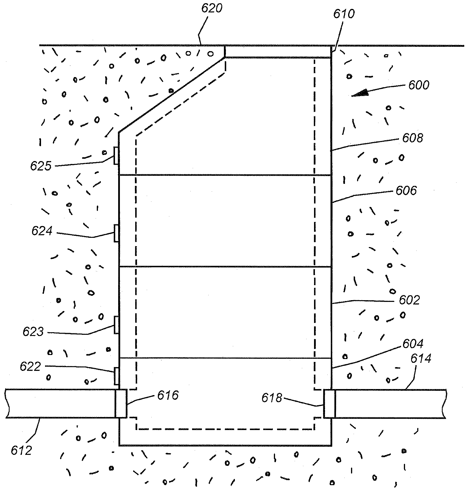
[0008]The RFID tag is programmed with information concerning the specific cast concrete element to which the RFID tag is affixed. The information stored on the RFID tag may be a serial number that is associated in a computer database with the name of the manufacturing facility that cast the concrete element, the date it was manufactured, the supplies used in its construction such as the concrete batch number and the type of reinforcing bar (“rebar”) used, pre-pour and post-pour inspections results, etc. In the preferred embodiment, the RFID tag is a passive tag. That is, it does not include a power supply.
[0009]In use, a mold is assembled to create a desired concrete component. Rebar is preferably positioned within the mold to provide the required strength to the finished concrete component. An RFID assembly whose RFID tag stores a unique serial number is selected for the concrete component being fabricated. The RFID assembly maybe hung off one of the rebar sections pending a pre-pour inspection of the mold. An inspector preferably checks to see that the mold has been correctly set-up, and that the rebar has...

Problems solved by technology

However, keeping accurate records has proven difficult.
For example, keeping track of pre-pour and post-pour inspection data, concrete batch number, intended construction project, etc., in an efficient manner is not currently possible.

Method used


Image

  • Radio frequency identification system and method for use in cast concrete components
  • Radio frequency identification system and method for use in cast concrete components
  • Radio frequency identification system and method for use in cast concrete components

Examples


Embodiment Construction

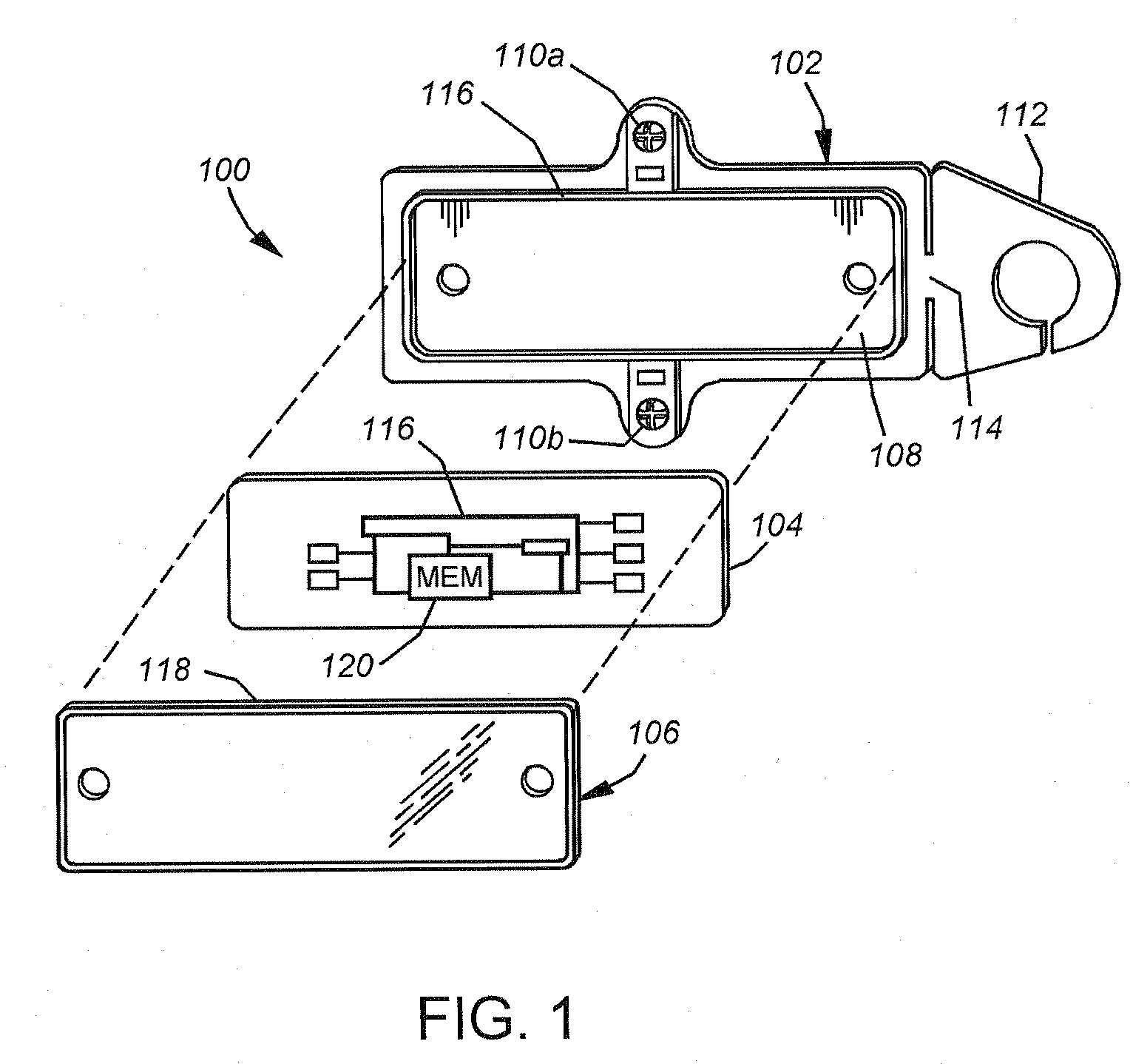
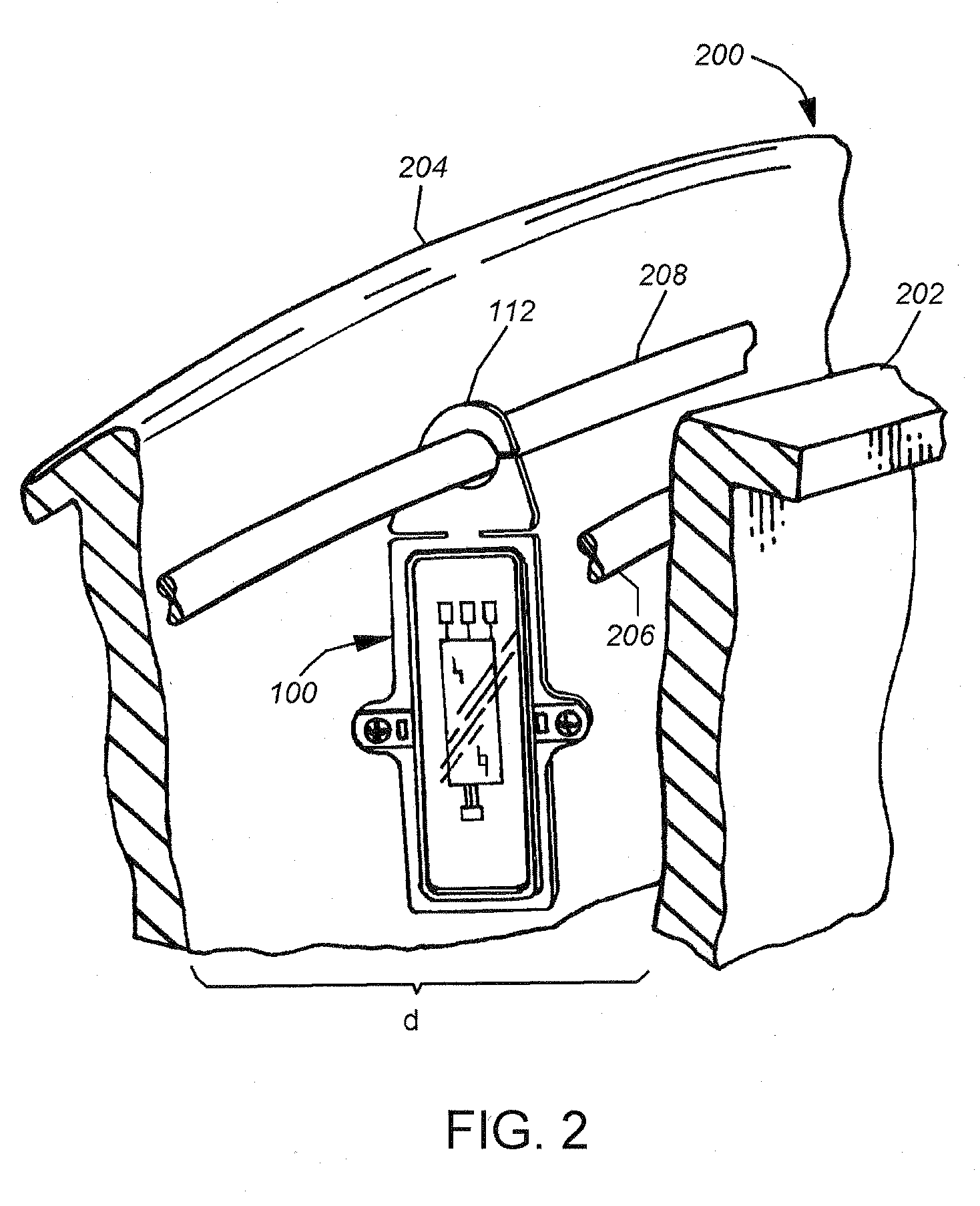
[0019]FIG. 1 is a highly schematic, exploded view of a radio frequency identification (RFID) assembly 100 according to a preferred embodiment of the present invention. The RFID assembly 100 includes a back plate 102, an RFID tag or transponder 104, and a cover 106. The back plate 102 has a substantially planar shape and includes a receiving area 108 sized and shaped to receive the RFID tag 104. In the embodiment of FIG. 1, the back plate 102 further includes a plurality of registration posts, such as registration posts 110a and 110b that extend substantially perpendicularly from the nominal plane of the back plate 102. The back plate 102 also may include a hook 112 located on one side of the back plate 102, such as side 114. As described in more detail below, the hook 112 is sized to fit over a section of reinforcing bar (“rebar”) so that the RFID assembly 100 may be suspended from the rebar.

[0020]Those skilled in the art will understand that the RFID assembly 100 may be circular, o...


PUM

PropertyMeasurementUnit
Thicknessaaaaaaaaaa
Transparencyaaaaaaaaaa
Wettabilityaaaaaaaaaa

Abstract

A radio frequency identification (RFID) assembly is configured for use with cast concrete components. The RFID assembly has a planar back plate having a plurality of break-away, registration posts extending perpendicular to the nominal plane of the back plate, and a plurality of gripping surfaces extending opposite the registration posts. The RFID assembly further includes a RFID transponder encapsulated between the back plate and a cover. The RFID transponder is programmed with information concerning the cast concrete component to which the RFID tag is affixed.

Description

BACKGROUND OF THE INVENTION[0001]1. Field of the Invention[0002]The present invention relates to systems and methods for applying identification information to components and, more specifically, to a radio frequency identification system and method for use with cast concrete components.[0003]2. Background Information[0004]Concrete elements or components, such as castings, are often used in the construction of civil engineering projects, such as water supply systems, wastewater systems, storm water systems and drainage systems. For example, a wastewater system typically includes a series of concrete manhole risers interconnected by concrete pipes. These elements are typically precast at a manufacturing facility, and then shipped to the location at which they are to be installed. The manhole risers and pipes are placed in ditches and connected in the desired manner. The ditches are then filled in, burying the manhole risers and pipes. Often, roads are then built over the manhole riser...

Claims


Application Information

Patent Timeline
IPC IPC(8): G08B1/08
CPCB28B23/00G06K2017/0077G06K19/07749B28B23/0031
Inventor TILSON, JR., THOMAS M.
Owner IDENCIA INC
Learn More