
User interface for welding power supply

Active Publication Date: 2009-03-19
LINCOLN GLOBAL INC
View PDF8 Cites 62 Cited by
  • Summary
  • Abstract
  • Description
  • Claims
  • Application Information

AI Technical Summary

Benefits of technology

[0014]In one aspect of the embodiments of the subject invention, the user interface facilitates real-time adjustment of the welding profile.

Problems solved by technology

For some weldments, it may be desirable to achieve deep penetration of the weld joint whereas in another application power supply settings for deep penetration may damage or destroy the adjoined materials.
If the welding operator provides erroneous data, or improperly calculates the setup parameters, poor weld quality or inefficient use of the welding machine and consumables may result.
However, less experienced welders may experiment by adjusting the welding profile in various ways until the desired weld has been achieved.
This can result in reduced quality, lost productivity and increased material costs.

Method used


Image

  • User interface for welding power supply
  • User interface for welding power supply
  • User interface for welding power supply

Examples


Embodiment Construction

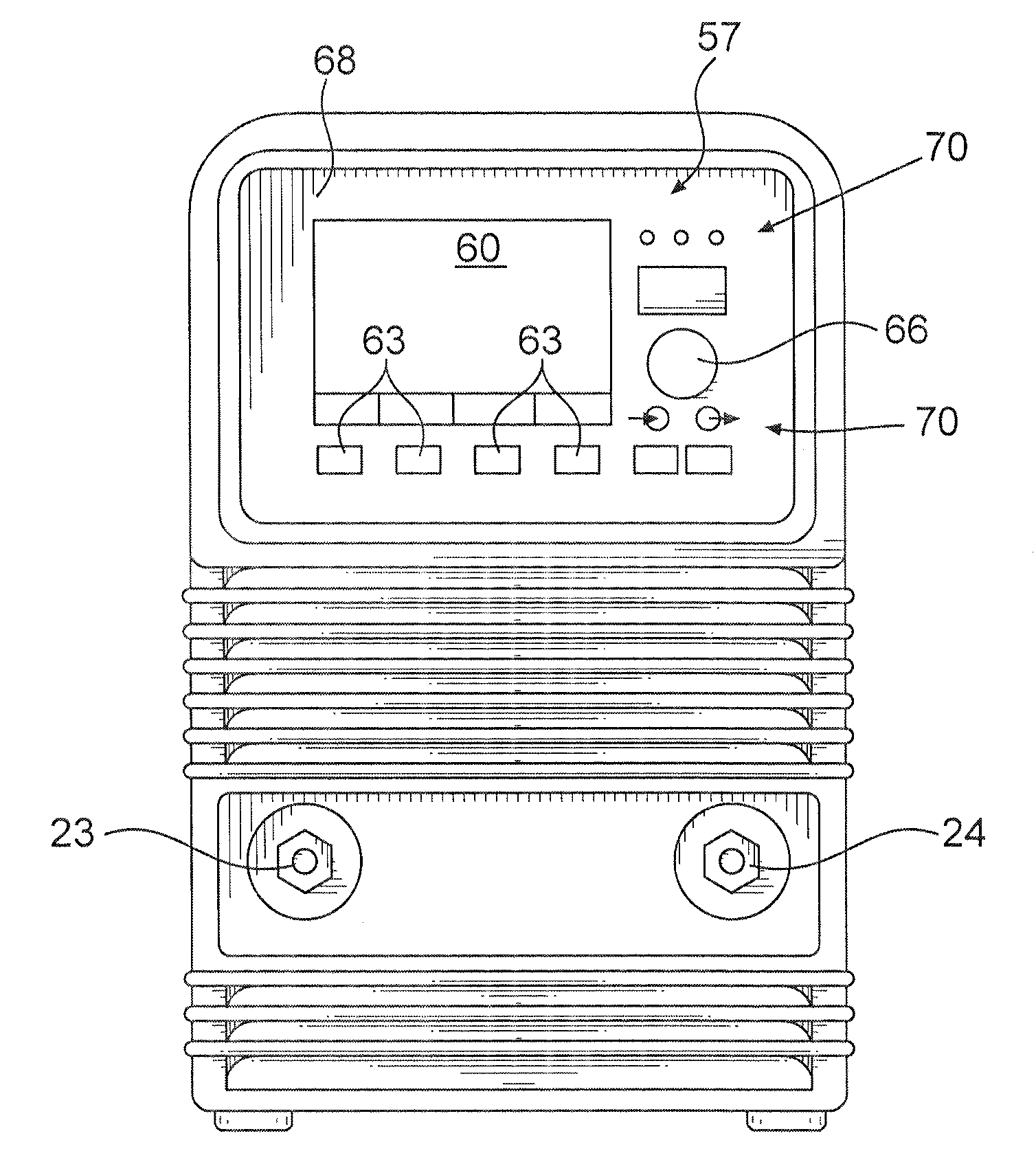
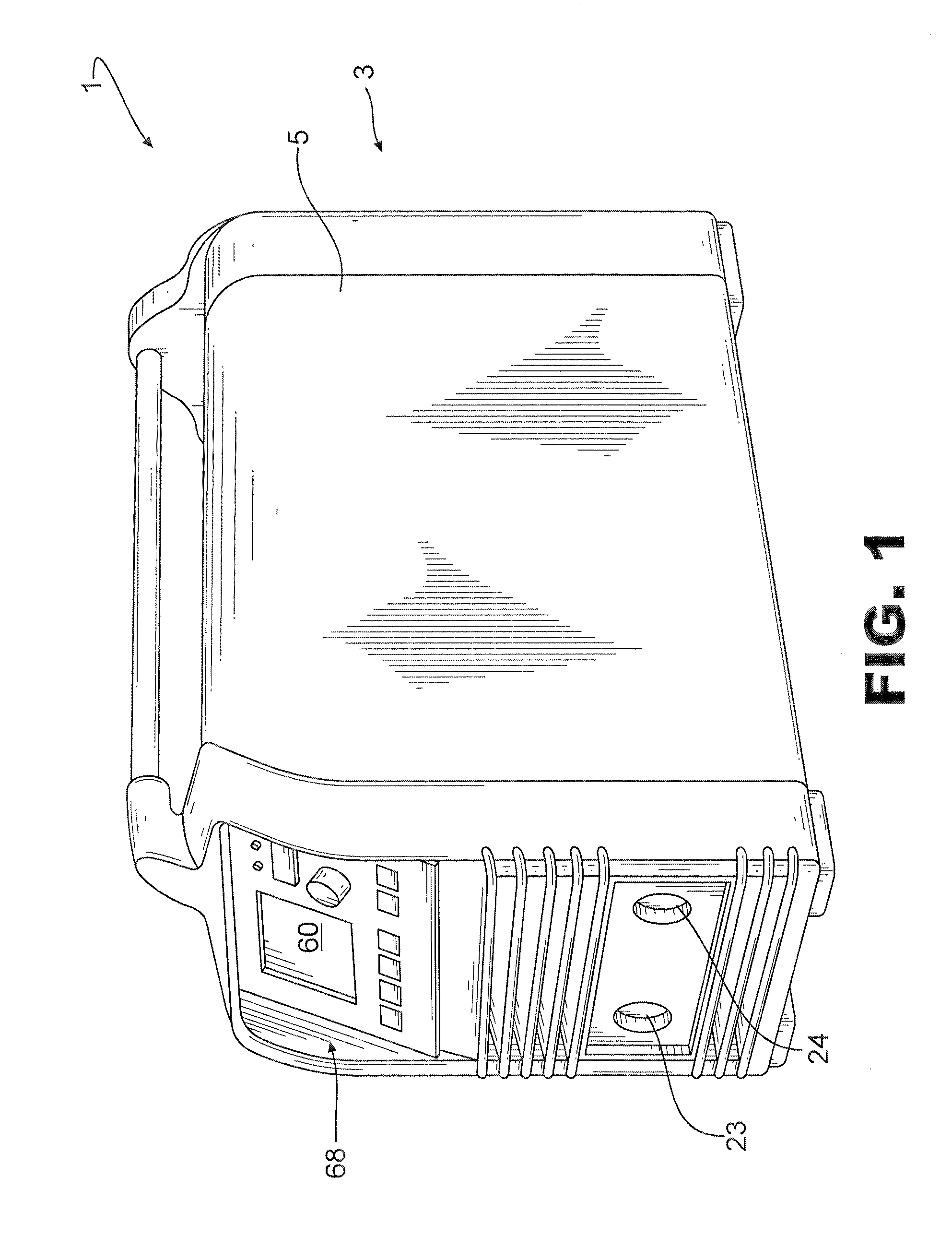
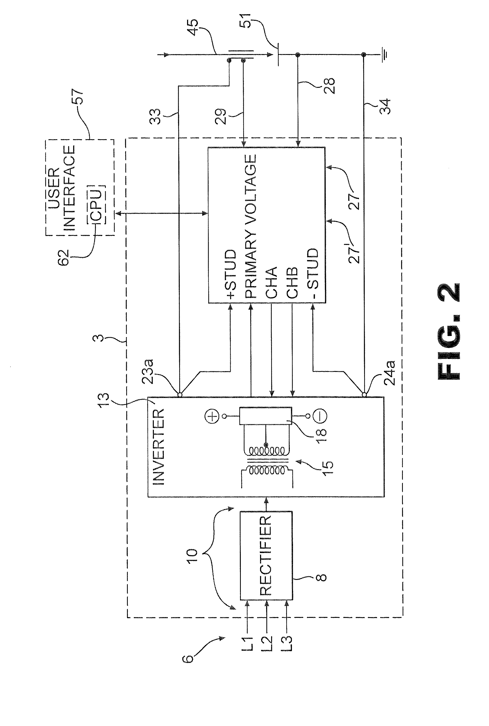
[0031]Referring now to the drawings wherein the showings are for purposes of illustrating embodiments of the invention only and not for purposes of limiting the same, FIG. 1 shows a welder depicted generally at 1. The welder 1 includes a power source 3 or welding power supply 3 enclosed within a housing 5. The welding power supply 3 described hereafter is exemplary in nature. Persons of ordinary skill in the art will readily understand the application of the embodiments of the subject invention to welding power supplies including both DC and AC output power as well as switched mode power supplies. Welding processes may include stick welding, gas metal arc welding (GMAW), gas tungsten arc welding (GTAW) and the like. The welding power supply 3 is illustrative as a switching inverter and is not intended to be limiting in any way. In the current embodiment, three phase power 6, shown by input power lines L1, L2 and L3 schematically represented in FIG. 2, may be directed to a power sour...


PUM

PropertyMeasurementUnit
Responsivityaaaaaaaaaa
Frequencyaaaaaaaaaa

Abstract

A welding power supply includes a user interface that allows the operator to adjust one or more welding parameters comprising a welding sequence for a welding process. The user interface may include a display, which may be a graphical display depicting the welding sequence and the one or more welding parameters. The user interface may further dynamically depict a pictograph, icon or other graphical image showing how changes to the one or more welding parameters will affect the welding process, which in an exemplary manner may be the welding bead profile and / or the welding arc profile.

Description

TECHNICAL FIELD[0001]The present invention pertains to controllers for welding power supplies and more particularly to controllers for welding power supplies having a graphical user interface that dynamically depicts the welding process.BACKGROUND OF THE INVENTION[0002]It is well known in the field of welding to adjust the parameters of a welding sequence to achieve a desired result. This may include setting the welding power supply at a specific voltage or current, or at a particular frequency. For some weldments, it may be desirable to achieve deep penetration of the weld joint whereas in another application power supply settings for deep penetration may damage or destroy the adjoined materials. Accordingly, the operator may adjust one or more welding parameters to match the material and joint configuration for a particular application.[0003]Gas Tungsten Arc Welding (GTAW) is one well known type of welding process, known also as Tungsten Inert Gas (TIG) welding. Gas-Metal-Arc-Weld...

Claims


Application Information

Patent Timeline
IPC IPC(8): B23K9/10B23K9/32
CPCB23K9/1062B23K9/1006
Inventor HARRIS, JAMES ALAN
Owner LINCOLN GLOBAL INC
Learn More