
Methods and apparatus for substrate processing

a substrate and processing method technology, applied in the direction of electrical equipment, electrical discharge tubes, decorative arts, etc., can solve the problems of defective devices, lack of uniformity during substrate processing, and defective devices

Active Publication Date: 2009-03-19
LAM RES CORP
View PDF2 Cites 35 Cited by
  • Summary
  • Abstract
  • Description
  • Claims
  • Application Information

AI Technical Summary

Benefits of technology

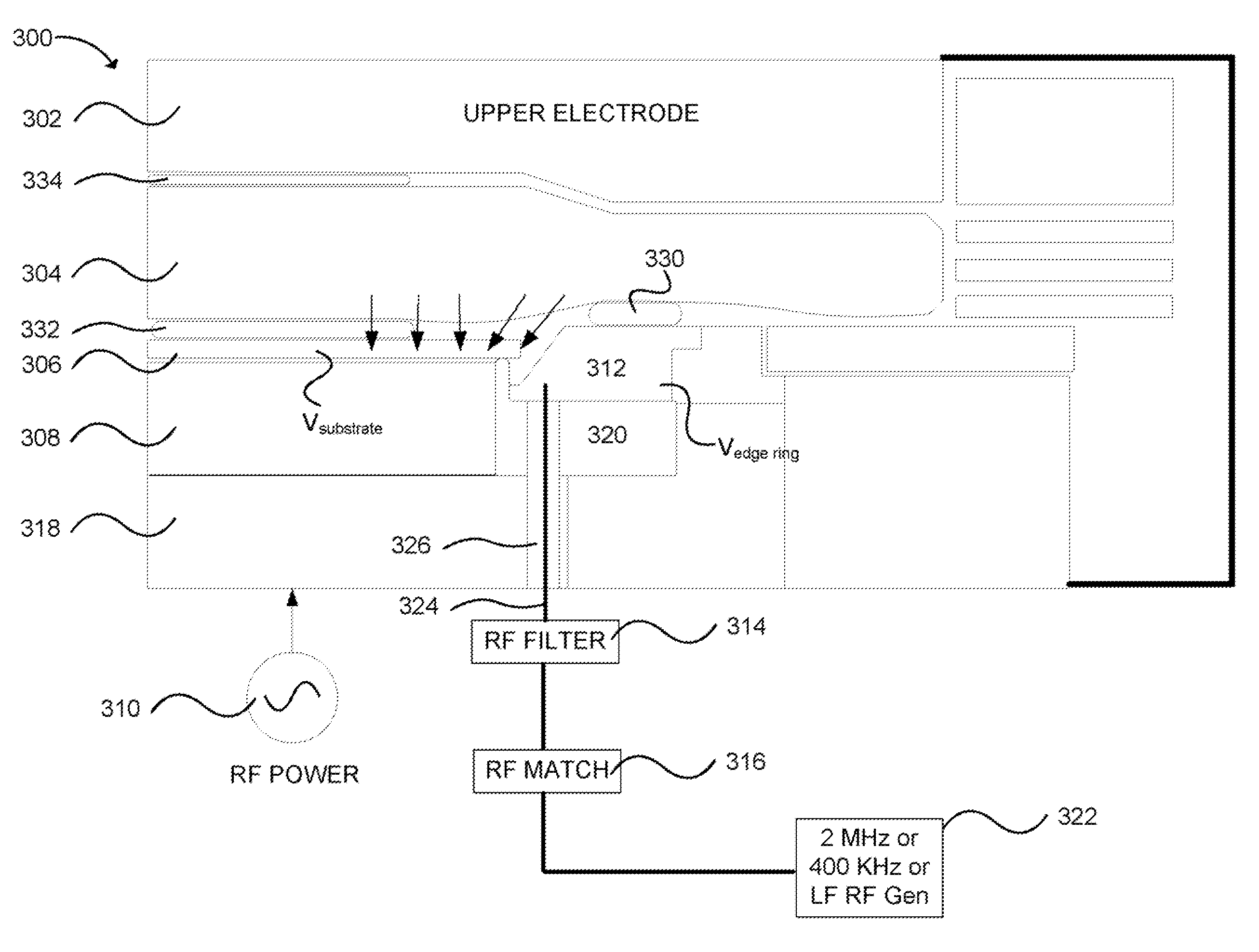
[0015]The invention relates, in an embodiment, to a method for processing a substrate in a plasma processing chamber. The substrate is disposed above a chuck and surrounded by an edge ring. The edge ring is electrically isolated from the chuck. The method includes providing first RF power to the chuck. The method also includes providing an edge ring RF voltage control arrangement. The edge ring RF voltage control arrangement is coupled to the edge ring to provide second RF power to the edge ring. The second RF power being delivered to the edge ring has a frequency of about 20 KHz to about 10 MHz, resulting in the edge ring having an edge ring potential. The method further includes generating a plasma within the plasma processing chamber to process the substrate. The substrate is being processed while the edge ring RF voltage control arrangement is configured to cause the edge ring potential to be substantially equal to a DC potential of the substrate while processing the substrate.

Problems solved by technology

A common cause of defective devices is the lack of uniformity during substrate processing.
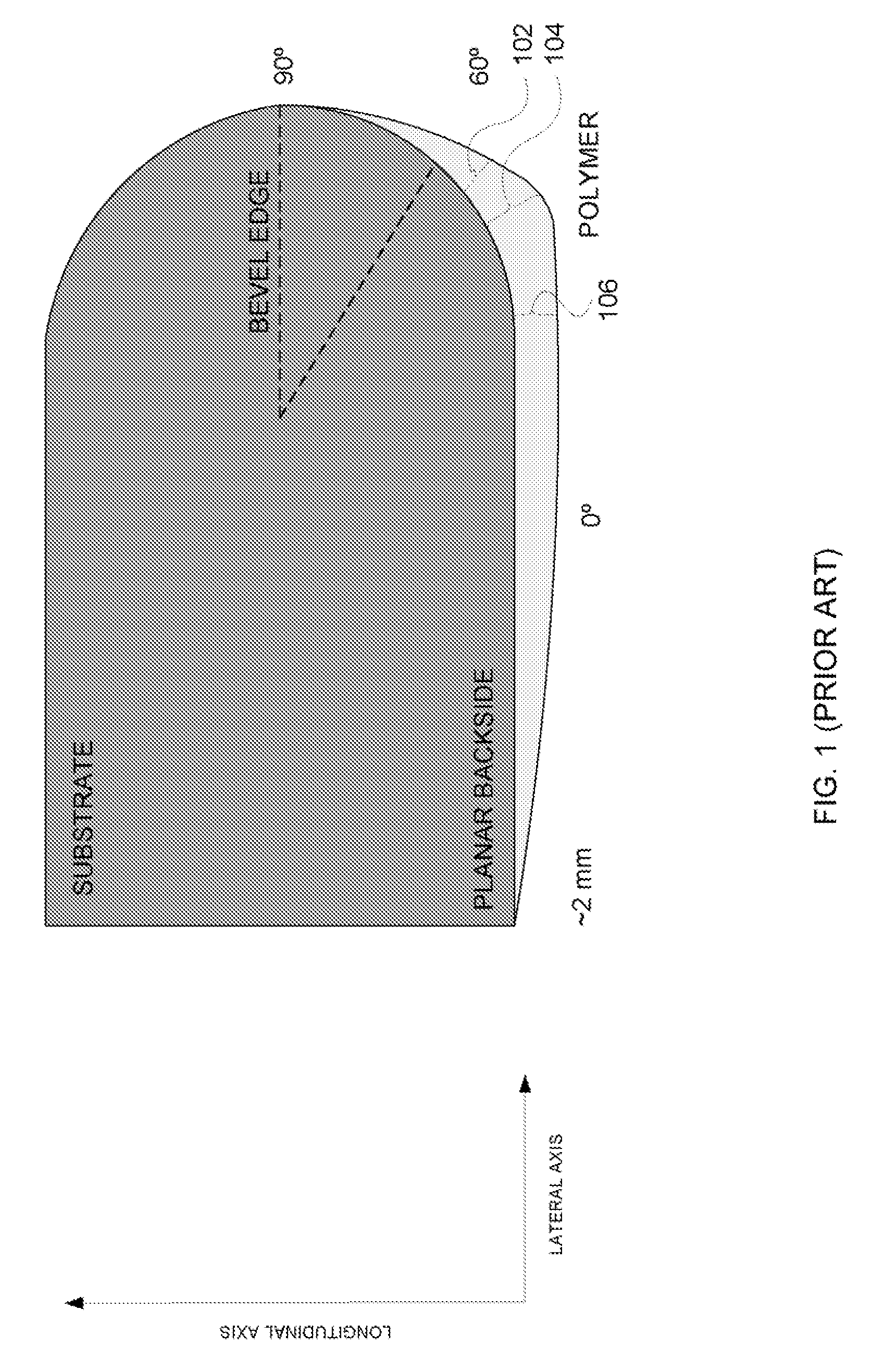
Another cause of defective devices may be due to polymeric by-products flaking off from the backside of one substrate onto another substrate during transport.
Due to the demand for higher performance devices, the pressure to further reduce substrate feature sizes, as well as the implementation of newer optimized substrate materials, has challenged current fabrication technologies.
For example, it is becoming increasing difficult to maintain the uniformity or process results from the center to the edge of larger substrates (e.g., >300 mm).
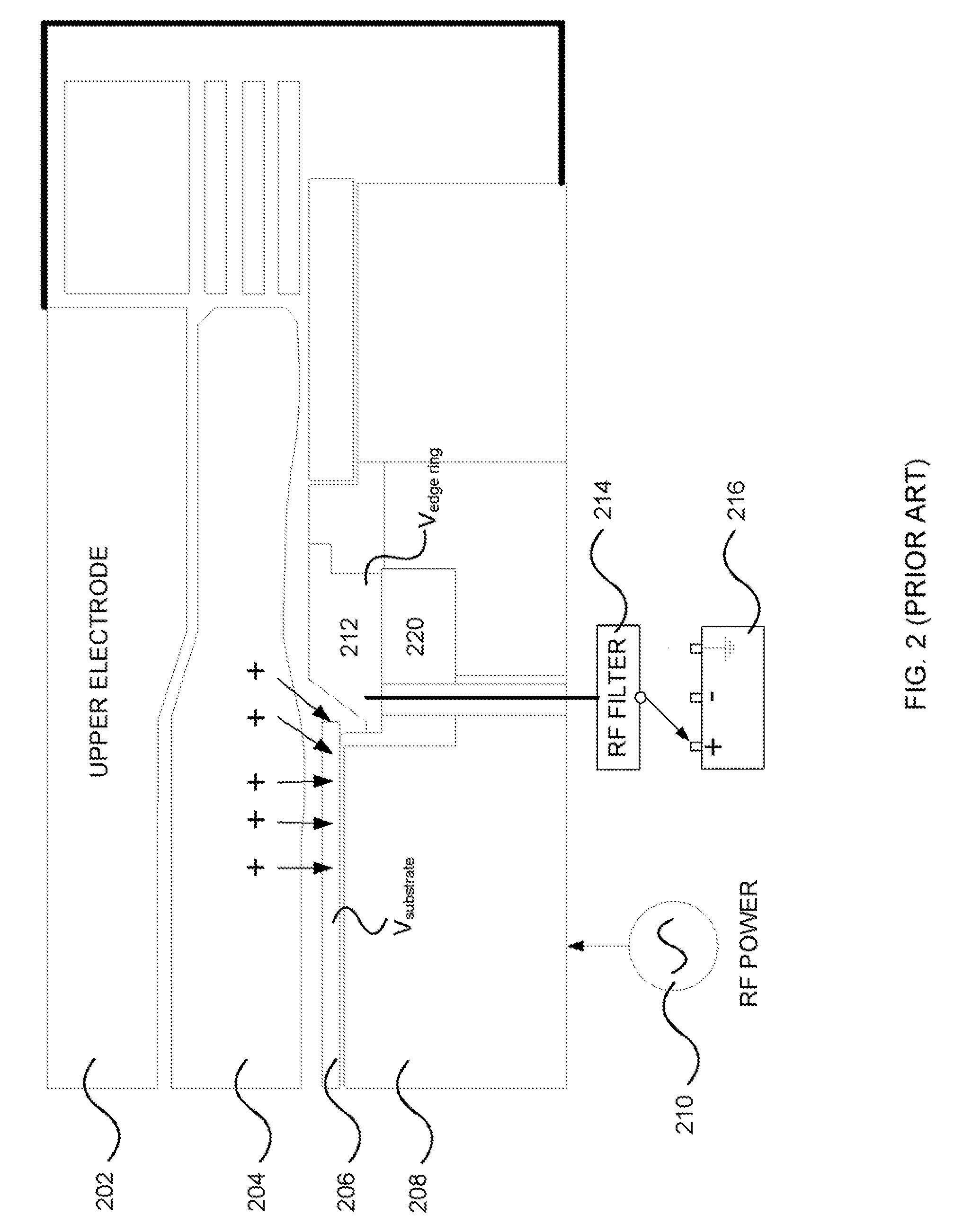
For example, the equipotential lines of the plasma sheath may become disrupted, causing non-uniform ion angular distribution around the substrate edge.
However, as successive polymer layers are deposited on the edge area as the result of several different etch processes, organic bonds that are normally strong and adhesive will eventually weaken and peel or flake off, often onto another substrate during transport.
As a higher positioned substrate is repositioned in the container, a portion of a polymer layer may fall on a lower substrate where dies are present, potentially affecting device yield.
In general, the greater the thickness of the polymer, the higher the probability that a portion of the polymer may become dislodged and fall onto another substrate or the chuck, potentially affecting manufacturing yield.
Thus, the angular ion distribution profile is substantially non-uniform, with a set of vectors that tend to point toward areas of lower potential, such as the substrate edge.
However, aforementioned prior art methods employing DC control on hot edge ring may require substantial DC power to sustain the required voltages, adding cost to the fabrication of devices.
In addition, arcing between the wafer edge and hot edge ring may cause pitting on substrate edge and damage to the devices, thereby reducing yield.

Method used


Image

  • Methods and apparatus for substrate processing
  • Methods and apparatus for substrate processing
  • Methods and apparatus for substrate processing

Examples


Embodiment Construction

[0024]The present invention will now be described in detail with reference to a few embodiments thereof as illustrated in the accompanying drawings. In the following description, numerous specific details are set forth in order to provide a thorough understanding of the present invention. It will be apparent, however, to one skilled in the art, that the present invention may be practiced without some or all of these specific details. In other instances, well known process steps and / or structures have not been described in detail in order to not unnecessarily obscure the present invention.

[0025]Various embodiments are described hereinbelow, including methods and techniques. It should be kept in mind that the invention might also cover articles of manufacture that includes a computer readable medium on which computer-readable instructions for carrying out embodiments of the inventive technique are stored. The computer readable medium may include, for example, semiconductor, magnetic, ...


PUM

PropertyMeasurementUnit
frequencyaaaaaaaaaa
frequencyaaaaaaaaaa
frequencyaaaaaaaaaa

Abstract

A method for processing a substrate in a plasma processing chamber is provided. The substrate is disposed above a chuck and surrounded by an edge ring. The edge ring is electrically isolated from the chuck. The method includes providing first RF power to the chuck. The method also includes providing an edge ring RF voltage control arrangement. The edge ring RF voltage control arrangement is coupled to the edge ring to provide second RF power to the edge ring resulting in the edge ring having an edge ring potential. The method further includes generating a plasma within the plasma processing chamber to process the substrate. The substrate is being processed while the edge ring RF voltage control arrangement is configured to cause the edge ring potential to be substantially equal to a DC potential of the substrate while processing the substrate.

Description

BACKGROUND OF THE INVENTION[0001]Advances in plasma processing have ilfacilitated growth in the semiconductor industry. Since the semiconductor industry is highly competitive, device manufacturers generally want to maximize yield and efficiently utilize the real estate available on a substrate. During plasma processing of the substrate, a plurality of parameters may need to be controlled to ensure high yield of devices being processed. A common cause of defective devices is the lack of uniformity during substrate processing. Factors that may affect uniformity are substrate edge effects. Another cause of defective devices may be due to polymeric by-products flaking off from the backside of one substrate onto another substrate during transport.[0002]Due to the demand for higher performance devices, the pressure to further reduce substrate feature sizes, as well as the implementation of newer optimized substrate materials, has challenged current fabrication technologies. For example, i...

Claims


Application Information

Patent Timeline
Patent Type & Authority Applications(United States)
IPC IPC(8): C23F1/00H01L21/306
CPCH01J37/32091H01J37/32642H01J37/32577H01J37/32568
Inventor DHINDSA, RAJINDERMARAKHTANOV, ALEXEI
Owner LAM RES CORP
Learn More