
Right side drive conversion

a technology of right side drive and conversion, which is applied in the direction of axle suspension, cycle equipment, vehicles, etc., can solve the problems of time-consuming

Inactive Publication Date: 2009-03-12
WHITE JOHN L +1
View PDF16 Cites 9 Cited by
  • Summary
  • Abstract
  • Description
  • Claims
  • Application Information

AI Technical Summary

Benefits of technology

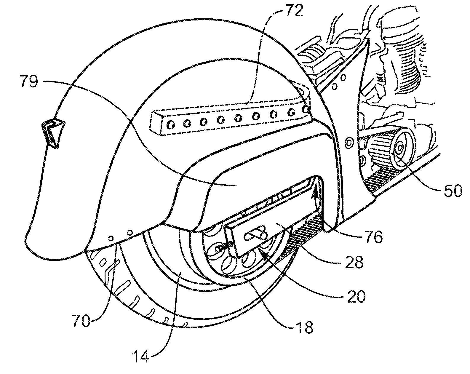
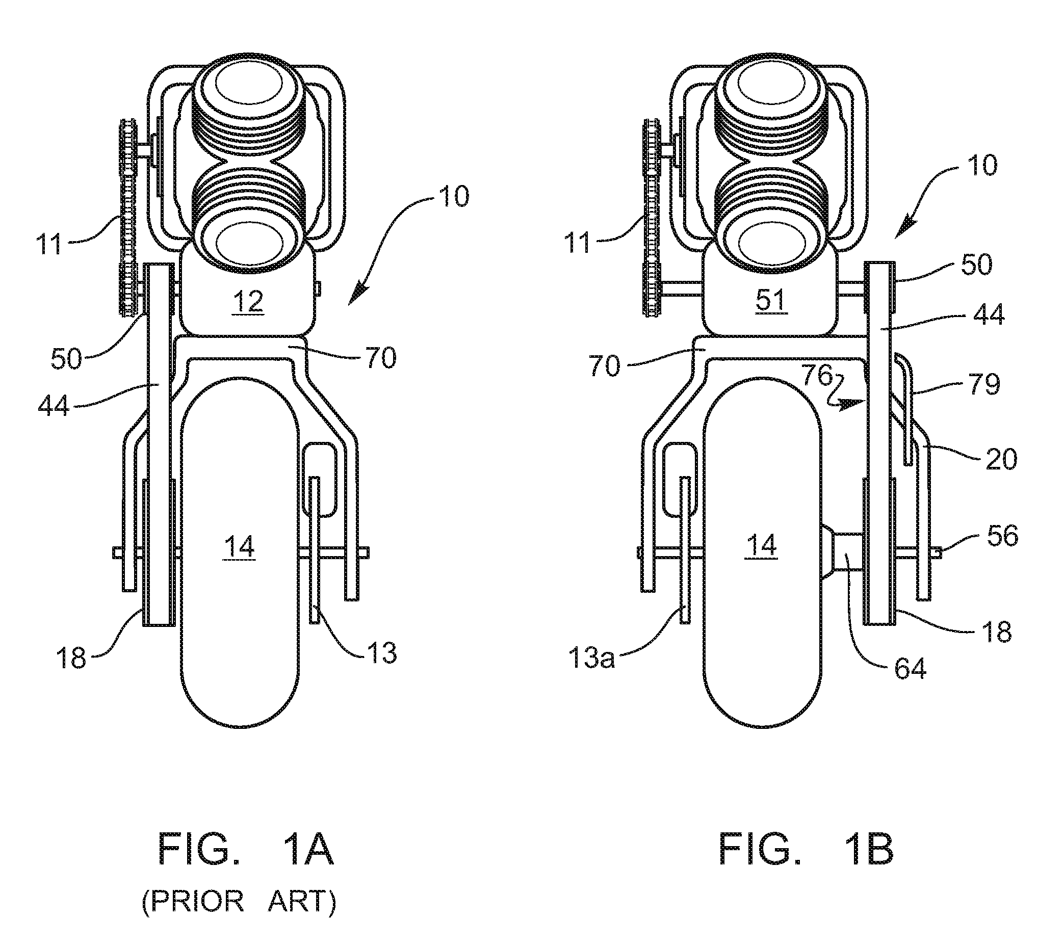
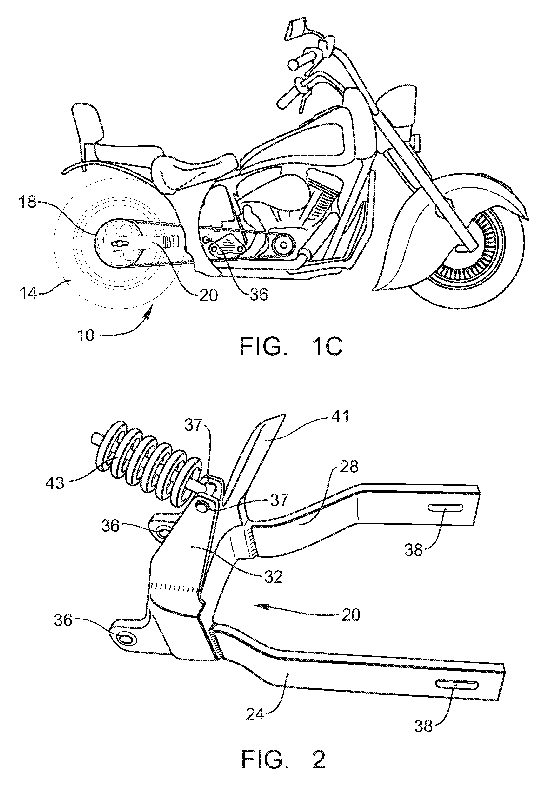
[0006]The present embodiments relate to converting a motorcycle with a left side drive to a right side drive. Again, the left side is the rider's left side when he is seated and facing forward. The right side is the rider's right side when the rider is seated and facing forward. This conversion may be done readily (in the field) and may be done with basic hand tools. The right side drive allows for a wider rear tire and a more balanced chassis. The drive pulley remains under the fender (on the inside of the fender) to allow for the use of saddlebags.
[0007]To accomplish the conversion, a small belt cover is removed. This belt cover is sometimes called the shroud or guard. The transmission drive pulley cover is also removed. The most time consuming part of this repair involves adjusting the belt tension. The total time spent may be approximately 30 to 60 minutes rather than 2 to 4 hours on conventional motorcycles. Generally, it is better to use a belt drive in these embodiments. While the use of a chain is clearly possible (and within the scope of the present embodiments), there may be issues involving the wear, maintenance, strength, noise and clean operation (i.e., grease flings everywhere) that make the use of the belt drive more desirable.

Problems solved by technology

The most time consuming part of this repair involves adjusting the belt tension.
While the use of a chain is clearly possible (and within the scope of the present embodiments), there may be issues involving the wear, maintenance, strength, noise and clean operation (i.e., grease flings everywhere) that make the use of the belt drive more desirable.

Method used


Image

  • Right side drive conversion
  • Right side drive conversion
  • Right side drive conversion

Examples


Embodiment Construction

[0027]The presently preferred embodiments of the present invention will be best understood by reference to the drawings, wherein like parts are designated by like numerals throughout. It will be readily understood that the components of the present invention, as generally described and illustrated in the figures herein, could be arranged and designed in a wide variety of different configurations. Thus, the following more detailed description of the present embodiments, as represented in the Figures, is not intended to limit the scope of the invention, as claimed, but is merely representative of presently preferred embodiments of the invention.

[0028]The present invention may be embodied in other specific forms without departing from its structures, methods, or other essential characteristics as broadly described herein and claimed hereinafter. The described embodiments are to be considered in all respects only as illustrative, and not restrictive. The scope of the invention is, there...


PUM


Abstract

A system and apparatus for converting a motorcycle with a left side drive into a motorcycle with a right side drive. This apparatus is particularly suitable for “Indian” brand, “Chief” model motorcycles manufactured in 2002 and thereafter. This apparatus includes a swing arm that facilitates the conversion and enables the use of wider rear wheels. A sprocket and drive pulley will also be added to the right side as part of the conversion process. A cutout in the fender may be added to accomplish the conversion. This apparatus is particularly suitable for “Indian”“PowerPlus Chiefs” (model year 2002 and later).

Description

CROSS-REFERENCED RELATED APPLICATIONS[0001]This application claims the benefit of U.S. Provisional Application No. 60 / 928,791, filed May 11, 2007. This prior patent application is expressly incorporated herein by reference.BACKGROUND OF THE INVENTION[0002]“Indian” brand motorcycles have been popular for many years. Standard “Indian” brand motorcycles included the drive for the motorcycle on the right side—i.e., on the rider's right side when the rider was facing forward.[0003]However, in 2002, the new company out of Gilroy, Calif. began producing a 2002 “Indian” brand motorcycle, namely “Indian” brand “Chief” models. This company produced a variety of “Chief” model motorcycles model year 2002 and later including the “Standard,”“Roadmaster,” Springfield,” and “Vintage”. (The “Vintage” was made in 2003 only). All of these submodels of the “Chief” motorcycle which either 2002 model year or after will be referred to herein as the “PowerPlus Chief.” For example, on the “PowerPlus Chief” ...

Claims


Application Information

Patent Timeline
Patent Type & Authority Applications(United States)
IPC IPC(8): B62D61/02
CPCB62M7/02B62K25/283
Inventor WHITE, JOHN L.MUTO, ANTHONY
Owner WHITE JOHN L
Learn More