
Plasma Display System

Inactive Publication Date: 2009-03-05
HITACHI LTD
View PDF2 Cites 1 Cited by
  • Summary
  • Abstract
  • Description
  • Claims
  • Application Information

AI Technical Summary

Benefits of technology

[0006]There is a need in the plasma display system for reduction in weight from viewpoints, for example, of wall-hanging applications and reduction in manufacturing cost. Use of a thinner sheet for the chassis is one possible way to achieve the foregoing purposes. A thinner chassis, however, results in a reduced stiffness. Strength of the chassis is then likely to be reduced against deformation that could occur when vibration or the like acts thereon during transportation. In the plasma display system disclosed in JP-A-2000-200046, there is still room for further improvement in terms of stiffness against deformation, though the frame disposed at the back surface of the chassis enhances the stiffness against deformation.
[0007]It is an object of the present invention to provide a plasma display system capable of enhancing stiffness against deformation.
[0009]In accordance with the first aspect of the present invention, each of the overhangs of the reinforcement member sticking out in a plurality of directions from the chassis includes the fixing means fixing the casing in place. As compared, for example, with an arrangement in which a fixing means is disposed in an inner portion on the back surface of the chassis, a range of positions of the chassis to be fixed with the casing by way of the fixing means can be expanded, thus enhancing strength of the chassis relative to end portion deformation (local deformation). In addition, when vibration due to transportation, or the like, acts, a local inertia force of the casing is applied to the fixing means. Intervention of the reinforcement member, however, helps reduce a force being applied to the chassis, thus enhancing stiffness against deformation.
[0010]According to the aspect of the present invention, the stiffness against deformation can be enhanced.

Problems solved by technology

A thinner chassis, however, results in a reduced stiffness.
In addition, when vibration due to transportation, or the like, acts, a local inertia force of the casing is applied to the fixing means.

Method used


Image

  • Plasma Display System
  • Plasma Display System
  • Plasma Display System

Examples


Embodiment Construction

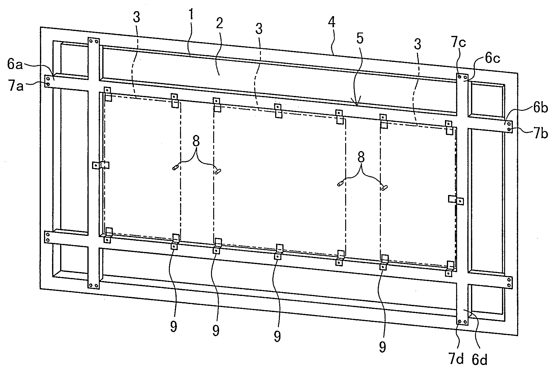
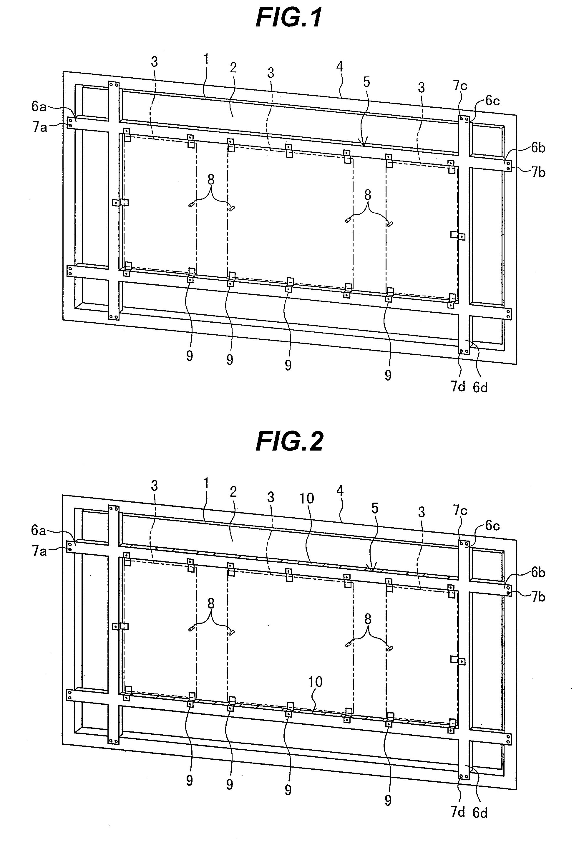
[0015]An embodiment of the present invention will be described below with reference to the drawings. FIG. 1 is a perspective view showing the structure of the plasma display system according to the embodiment of the present invention.

[0016]Referring to FIG. 1, the plasma display system includes a plasma display panel (hereinafter abbreviated to “PDP”) 1, a sheet-like chassis 2 bonded to a back surface of the PDP 1 with an adhesive or the like, a circuit board 3 outputting an electric signal to the PDP 1, and a casing 4 accommodating therein the PDP 1, the chassis 2, and the circuit board 3.

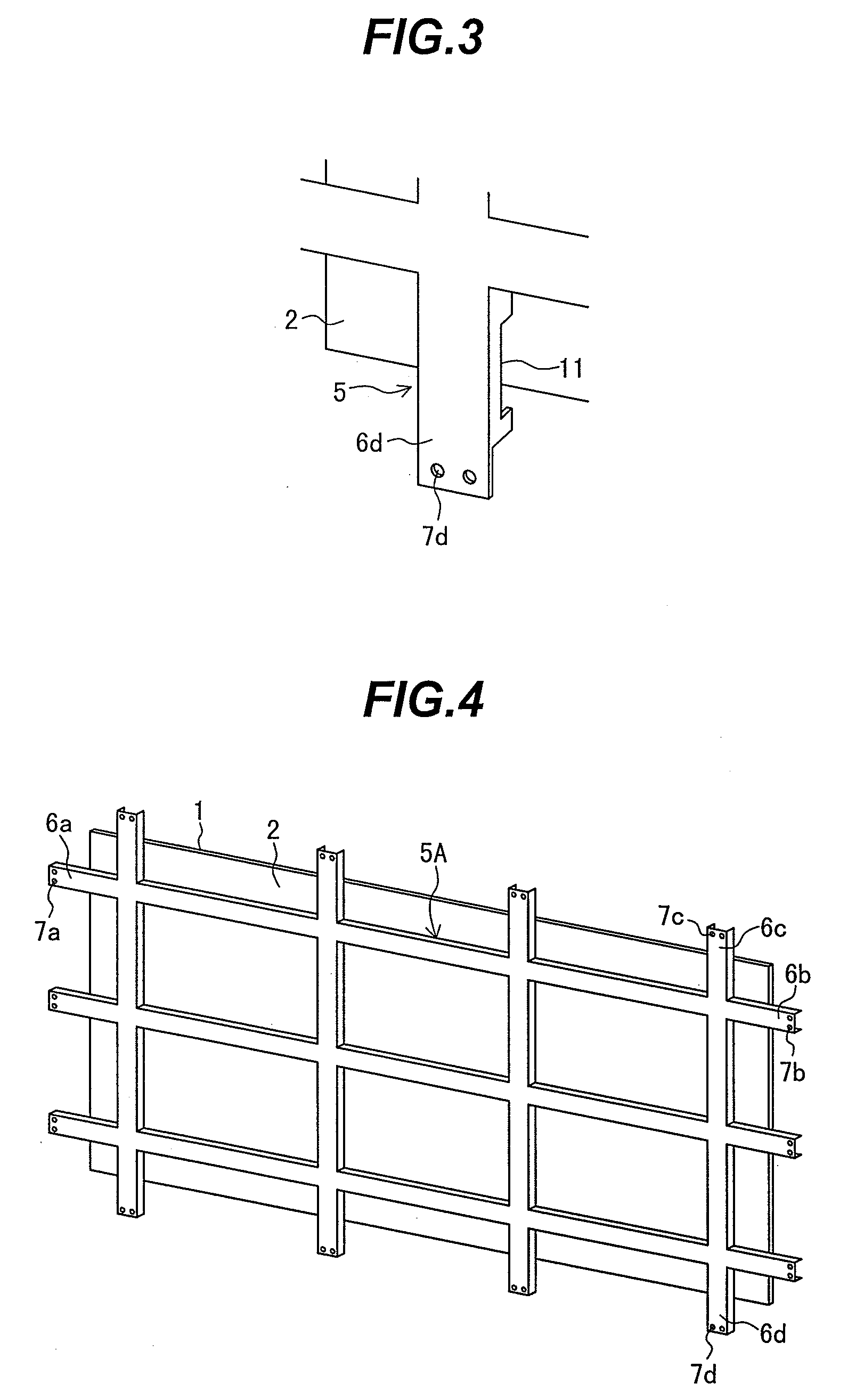
[0017]A reinforcement member 5 having, for example, a C-shaped cross section is disposed on a back surface of the chassis 2 so as to form a lattice. In accordance with this embodiment of the present invention, the reinforcement member 5 includes two each sub-members extending in a longitudinal, or a long edge, direction (horizontal direction in FIG. 1) and a short edge direction (vertical directio...


PUM


Abstract

A plasma display system capable of enhancing stiffness against deformation. The system comprising a plasma display panel (PDP) 1; a sheet-like chassis 2 bonded to a back surface of the PDP 1; a circuit board 3 outputting an electric signal to the PDP 1; a casing 4 accommodating therein the PDP 1, the chassis 2, and the circuit board 3; a reinforcement member 5 disposed as an adjunct at a back surface of the chassis 2, the reinforcement member 5 extending in a plane direction of the chassis 2 to stick outwardly therefrom; and a fixing means (e.g. through holes 7a to 7d) disposed in each of overhangs 6a to 6d of the reinforcement member 5 sticking out in a plurality of directions from the chassis 2, the fixing means fixing the casing 4 in place.

Description

BACKGROUND OF THE INVENTION[0001]1. Field of the Invention[0002]The present invention relates to a plasma display system for displaying images with a plasma display panel.[0003]2. Description of Related Art[0004]A plasma display system typically includes a plasma display panel (hereinafter abbreviated to “PDP”), a sheet-like chassis bonded to a back surface of the PDP, a circuit board outputting an electric signal to the PDP, and a casing accommodating therein the PDP, the chassis, and the circuit board (see, for example, JP-A-2000-200046).[0005]A plasma display system disclosed in JP-A-2000-200046 includes a ladder-like frame disposed as an adjunct at a back surface of a chassis. The back surface of the chassis also includes a first boss and a second boss disposed on an inner side thereof. The first boss has a threaded hole formed therein for mounting a circuit board. The second boss has a threaded hole formed therein for mounting a back cover. The circuit board is secured in place...

Claims


Application Information

Patent Timeline
IPC IPC(8): G06F1/16G09F9/00H04N5/64
CPCH05K5/02H01J11/34
Inventor FUKUYAMA, MAYUMITANOKUCHI, AKITO
Owner HITACHI LTD
Learn More