Apparatus for assisting write operation using high frequency magnetic field in disk drive
a technology of high frequency magnetic field and disk drive, which is applied in the field of disk drive, can solve the problems of inability to easily promote ultra-high recording density, method problems, and inability to reduce coercive force at the recording part,
- Summary
- Abstract
- Description
- Claims
- Application Information
AI Technical Summary
Problems solved by technology
Method used
Image
Examples
first embodiment
[0035](Configuration of the Disk Drive)
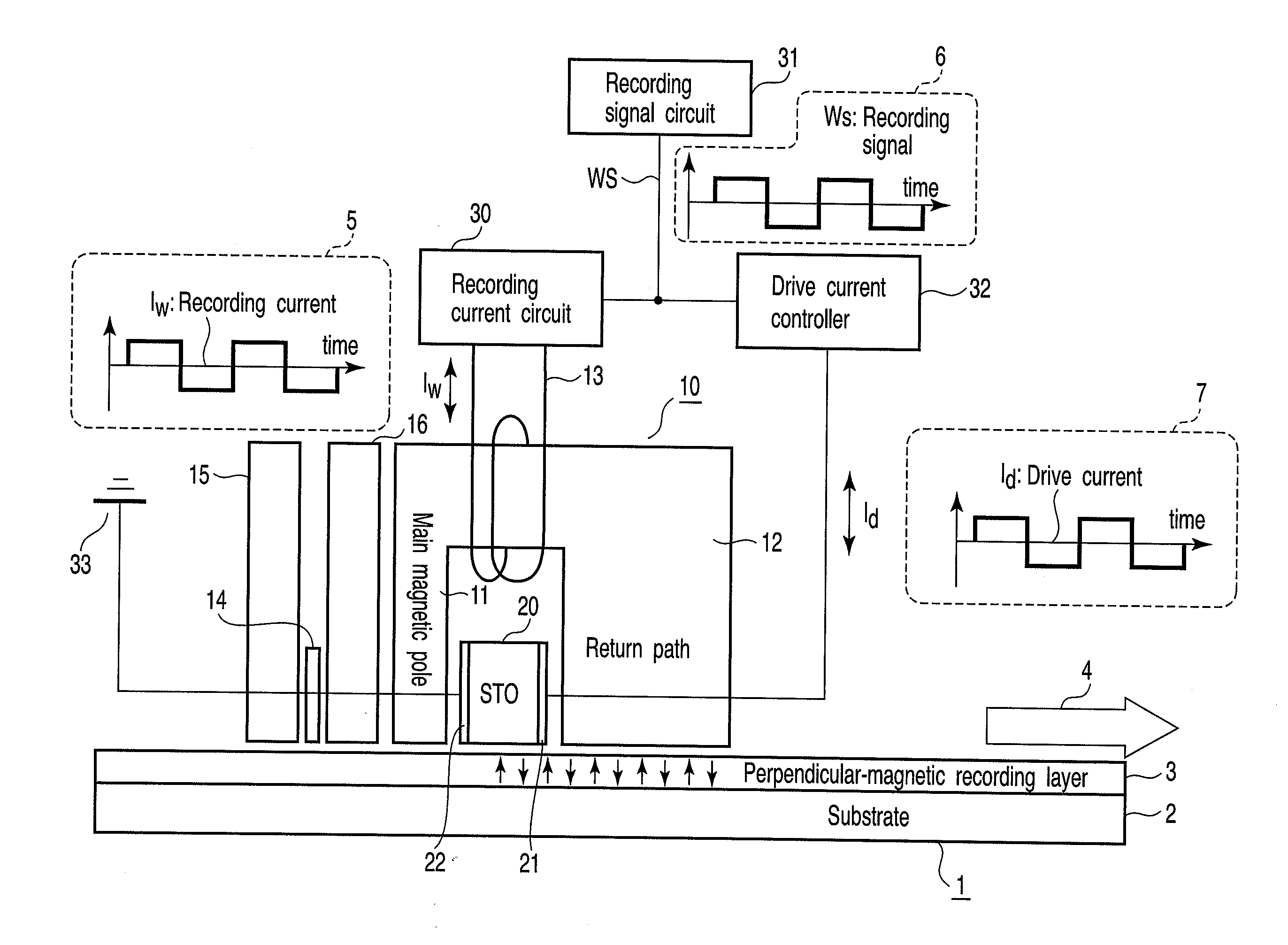
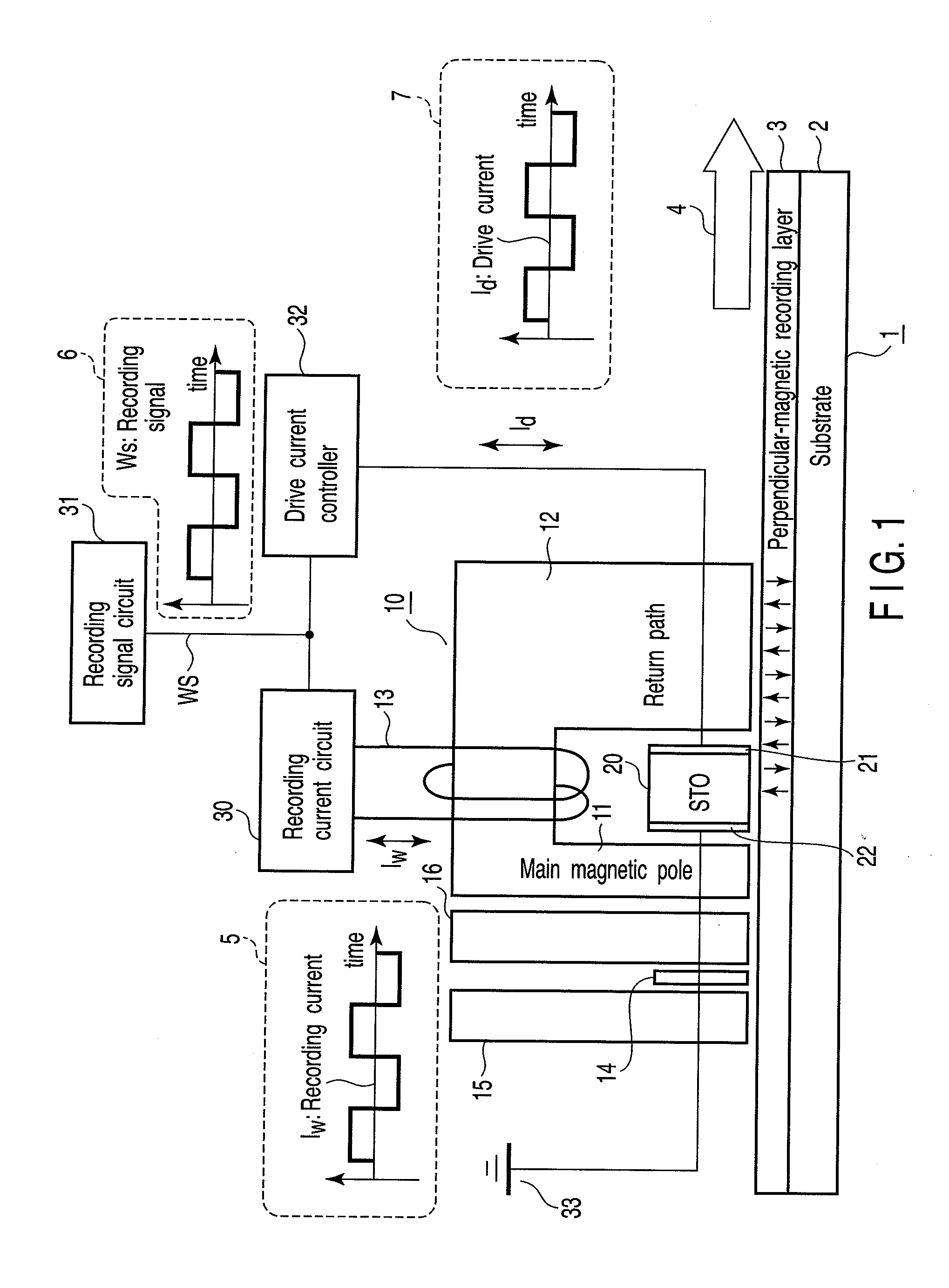
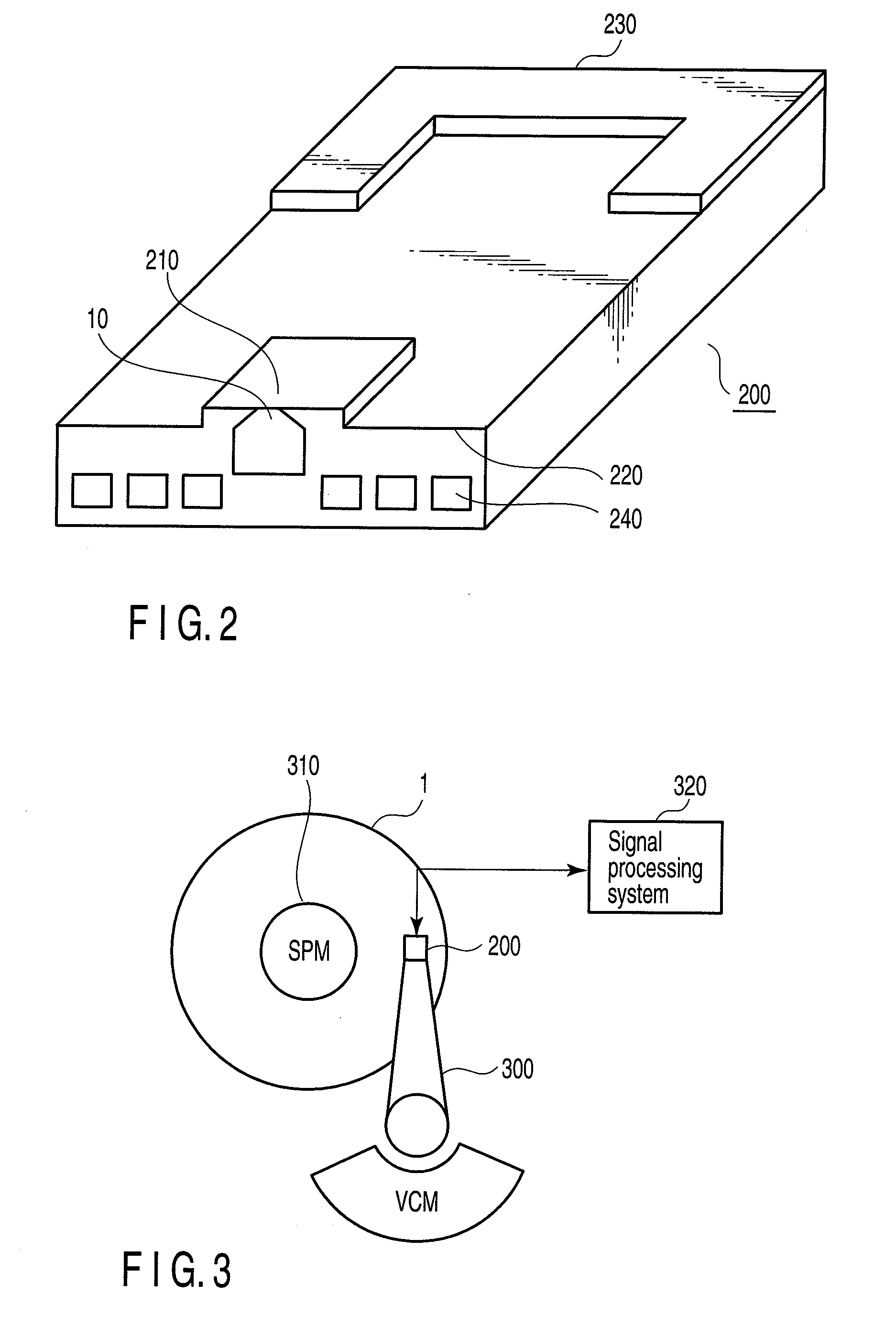
[0036]FIG. 1 is a diagram showing the major components of a disk drive according to a first embodiment of the present invention. FIG. 2 is a diagram explaining the structure of the head slider according to this embodiment. FIG. 3 is a diagram schematically illustrating the configuration of the disk drive according to this embodiment. FIG. 4 is a diagram showing the structure of the spin torque oscillator incorporated in the first embodiment.
[0037]The disk drive according to the present embodiment has a disk 1 and a magnetic head 10. The disk 1 is a perpendicular-magnetic recording medium. The magnetic head 10 has the function of performing high frequency assisted writing. As FIG. 2 shows, the magnetic head 10 is mounted on the distal end of a head slider 200 and located near a surface 210 that faces the disk 1.
[0038]The head slider 200 is made of a composite material composed of, for example, aluminum oxide (Al2O3) and titanium carbide (TiC). T...
second embodiment
[0074]FIG. 12 is a diagram showing the major components of a disk drive according to a second embodiment of the present invention. Of the components shown in FIG. 12, those identical to the components shown in FIG. 1 are designated by the same reference numbers and will not be described in detail.
[0075]In the first method described above, bias magnetic fields, each having a specific intensity, are applied to the oscillation layer 25 of the STO 20, respectively from the bias layer (layer 25b shown in FIG. 4) and the spin injection layer 23. Therefore, a DC drive current (IdDC) of a prescribed value corresponding to the operating point shown in FIG. 8 should be supplied to the oscillation layer 25 to make the layer 25 oscillate at a prescribed frequency even if it is applied with no leakage recording magnetic field Hex from the main magnetic pole 11.
[0076]In view of this, the drive current controller 32 is configured to supply a drive current Id (=IdAC+IdDC) to the STO 20 in the prese...
third embodiment
[0079]FIG. 13 is a diagram showing the major components of a disk drive according to a third embodiment of the present invention. Of the components shown in FIG. 13, those identical to the components shown in FIG. 1 are designated by the same reference numbers and will not be described in detail.
[0080]In the second method described above, the drive current Id supplied to the STO 20 must be inverted in polarity in synchronism with the polarity inversion of the recording current Iw in order to stabilize the oscillation frequency of the STO 20. In addition, the drive current Id must be changed in amplitude, depending upon the polarity of the driving current Id.
[0081]In the present embodiment, the drive current controller 32 is configured to supply a drive current Id (=IdAC+IdDC) to the STO 20. The current Id changes in synchronism with the changes of the recording signal Ws and recording current Iw and changes in amplitude in accordance with its polarity.
[0082]The recording signal circ...
PUM
| Property | Measurement | Unit |
|---|---|---|
| oscillation frequency | aaaaa | aaaaa |
| recording current | aaaaa | aaaaa |
| polarity | aaaaa | aaaaa |
Abstract
Description
Claims
Application Information
 - R&D
- Intellectual Property
- Life Sciences
- Materials
- Tech Scout
- Unparalleled Data Quality
- Higher Quality Content
- 60% Fewer Hallucinations
Browse by: Latest US Patents, China's latest patents, Technical Efficacy Thesaurus, Application Domain, Technology Topic, Popular Technical Reports.
© 2025 PatSnap. All rights reserved.Legal|Privacy policy|Modern Slavery Act Transparency Statement|Sitemap|About US| Contact US: help@patsnap.com


