
Computer Input Device

a computer and input device technology, applied in computing, instruments, electric digital data processing, etc., can solve the problems of limiting the size of the screen that can be included, hand, arm, wrist and finger movements of keyboard users, and the difficulty of people with large fingers using small keypads, so as to reduce the risk of repetitive strain injury

Inactive Publication Date: 2009-02-26
S O I TEC SILICON ON INSULATOR THECHNOLOGIES
View PDF8 Cites 98 Cited by
  • Summary
  • Abstract
  • Description
  • Claims
  • Application Information

AI Technical Summary

Benefits of technology

[0056]The device when applied to a computer preferably also includes a wrist support, e.g. supporting the base of the hand, to reduce any risk of repetitive strain injury. If desired, the wrist support may be linked to means for controlling the power supply or power management for the device, for example a power ‘on / off’ switch or power ‘stand-by’ switch, so that the power may be switched on or off, or otherwise controlled, by the user through the wrist support.

Problems solved by technology

This is slow, and the hand, arm, wrist and finger movements associated with keyboard usage are also associated with illnesses such as repetitive strain injuries.
Although a mobile phone keypad is smaller than a computer keyboard, it is large compared with the overall size of the phone and limits the size of screen that can be included.
Small keypads are also more difficult to use for people with large fingers.
Keyboards on PDAs and small portable computers are difficult and slow to use because of their small size.

Method used


Image

  • Computer Input Device
  • Computer Input Device
  • Computer Input Device

Examples


Embodiment Construction

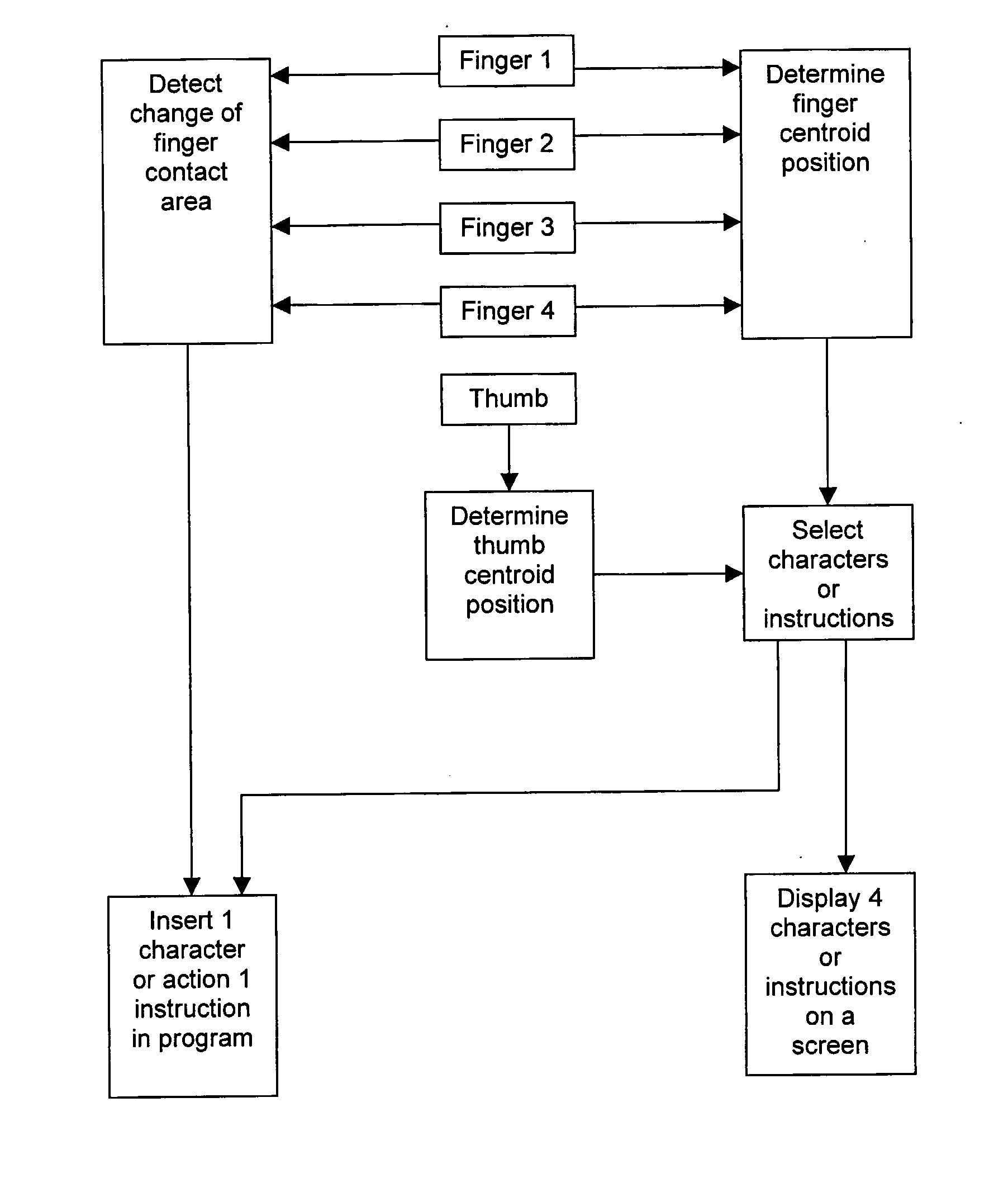
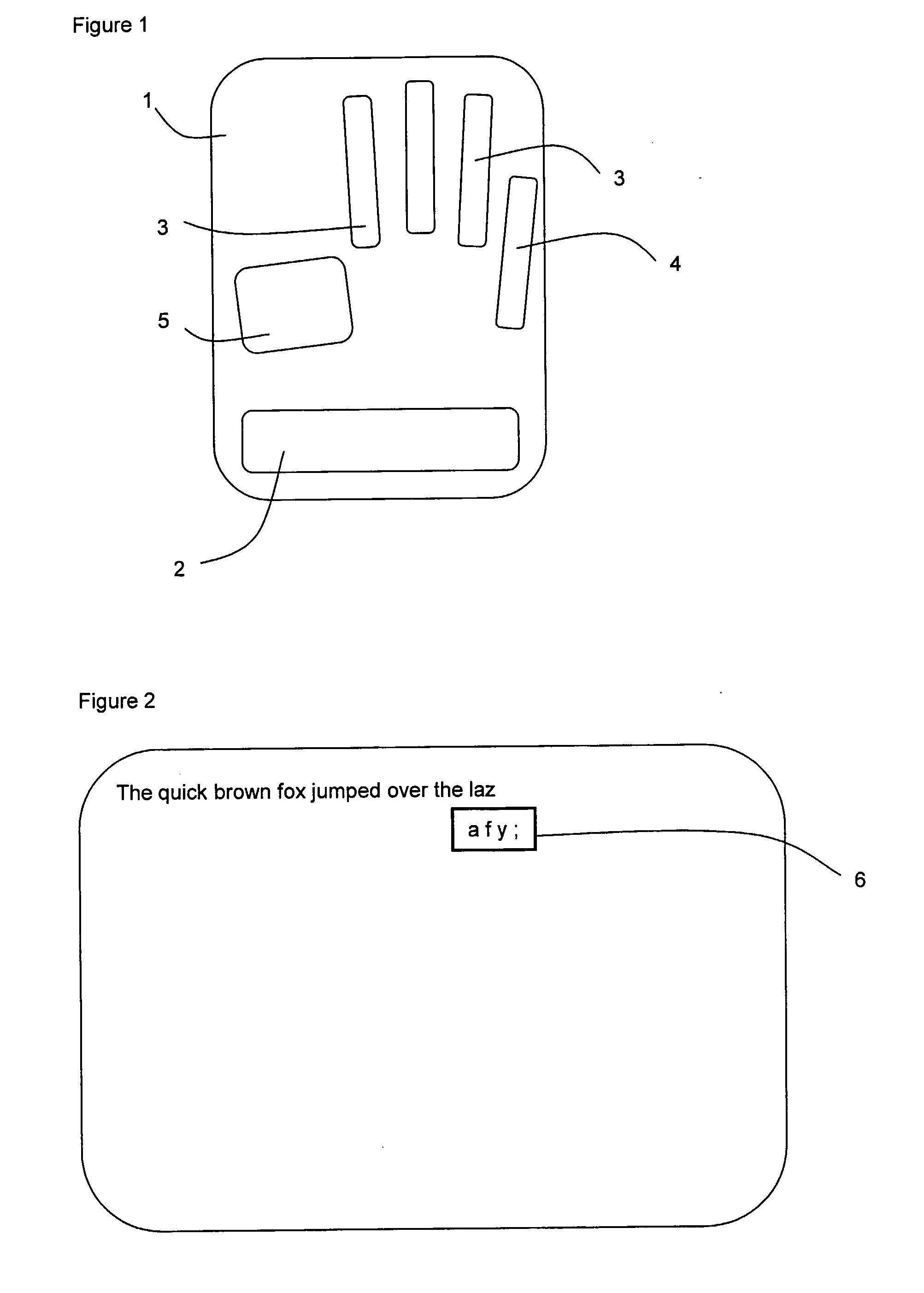
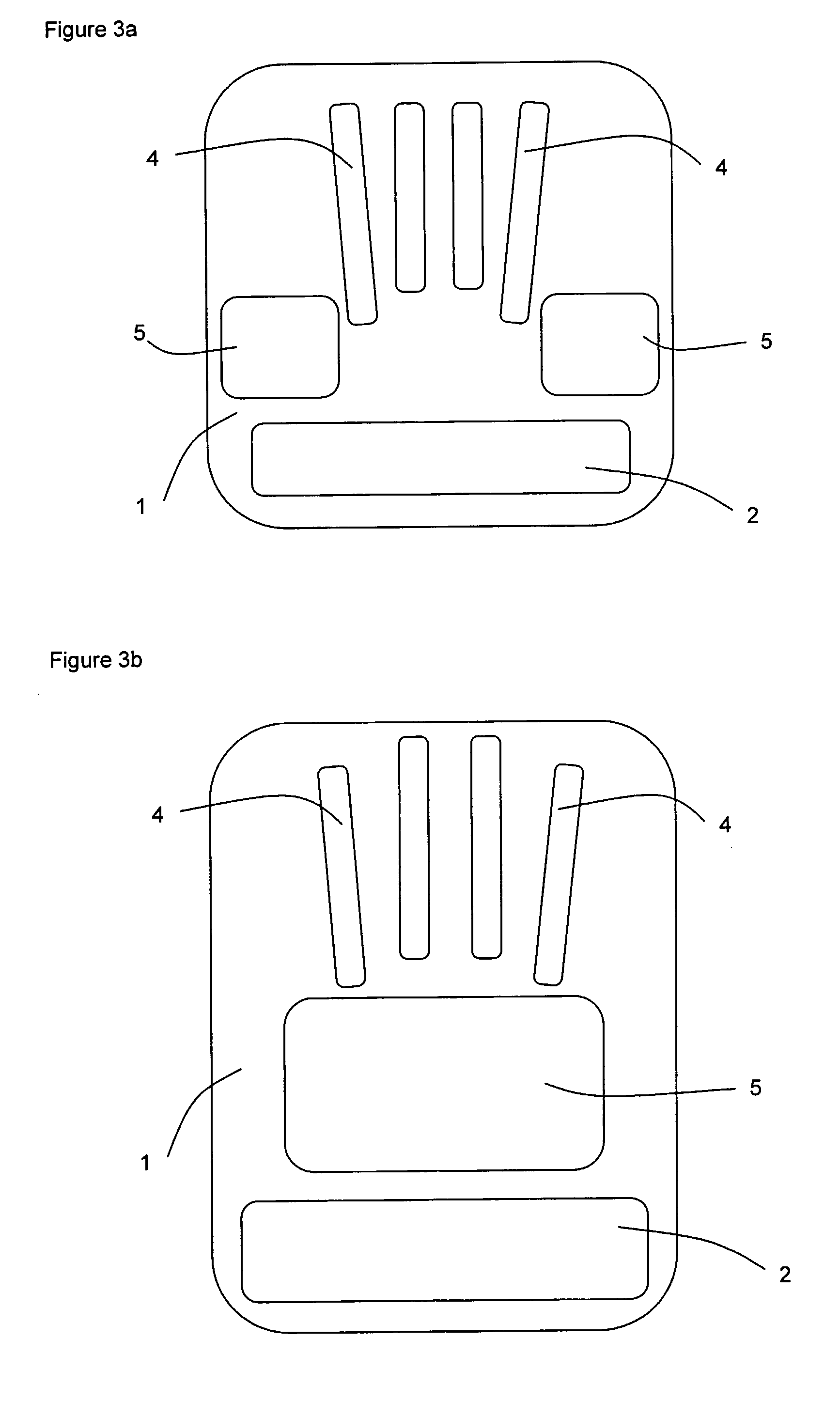
[0036]This invention uses small movements or changes in pressure of the fingers of one or more hands each to select one of a plurality of characters or instructions for display on the screen of an electronic device and to select one of these displayed characters or instructions to be entered into the electronic device. In one aspect of the invention, the movement of each finger is made along one of a corresponding number of touch pads and the finger's position on its touch pad determines the character or instruction to be selected. The entry is effected by momentarily changing the pressure of the corresponding finger on the touch pad such as by tapping or lifting the corresponding finger. The position of the thumb on its own touch pad determines which of a plurality of sets of characters the fingers present for display. An alternative aspect of the invention uses pressure cups instead of touch pads. In this aspect, the finger tips and the thumb sit in small cups and the characters a...


PUM


Abstract

A device (1) for data entry into an electronic device such as a computer, personal digital assistant (PDA) or mobile phone is provided, comprising thumb and finger touch pads (5,3), arranged on the device in a pattern corresponding to the natural thumb and finger tip positions of the thumb and fingers when relaxed; each finger pad (3) extending in backward and forward directions; the thumb pad (5) extending in left and right directions; position detecting means to detect the position of the thumb and each finger tip along each of the thumb and finger pads (5,3); finger data selection means to select for each finger a character or instruction corresponding to the detected position of a finger tip when in contact with a finger pad (3); thumb option selection means to select an option corresponding to the detected position of the thumb when in contact with the thumb pad (5); selection display means to display the character or instruction selected on each finger pad (3) according to the option selected on the thumb pad (5); and data entry detecting means to detect lifting of a finger from a finger pad (3) and enter a character or instruction into the electronic device based on the character or instruction selected on the finger pad (3) for which lifting is detected and based on the option selected on the thumb pad (5). Instead of touch pads, pressure cups can be used.

Description

TECHNICAL FIELD[0001]This invention relates to a device and method for entering characters or instructions into an electronic device such as a computer, personal digital assistant (PDA) or mobile telephone. This invention offers an alternative to conventional devices for entering characters or instructions into an electronic device, such as keyboards, keypads or touch screens.BACKGROUND ART[0002]People frequently need to enter alphanumeric data, punctuation or instructions into an electronic machine. Generally, a computer user enters this using a keyboard and a pointing device such as a mouse or a touch pad, a mobile telephone user enters text and numbers using the phone's numerical keypad and a PDA user enters data using devices including a small keyboard or a pointing device on a touch screen.[0003]Keyboards enable fast data entry if the operator can touch-type; that is to type while looking at the screen. Many users have not learnt this skill and rely on the slower technique know...

Claims


Application Information

Patent Timeline
IPC IPC(8): G06F3/041
CPCG06F3/0235G06F3/0219
Inventor MICKELBOROUGH, PHILLIP JOHN
Owner S O I TEC SILICON ON INSULATOR THECHNOLOGIES
Learn More