Terminal module for rotating electric machine, and rotating electric machine

a technology of terminal modules and electric machines, applied in the direction of electrical apparatus, dynamo-electric machines, supports/enclosements/casings, etc., can solve the problem of difficult automatic assembly and achieve the effect of facilitating automatic assembly

Inactive Publication Date: 2009-02-12
TOYOTA JIDOSHA KK +3
View PDF13 Cites 60 Cited by
  • Summary
  • Abstract
  • Description
  • Claims
  • Application Information

AI Technical Summary

Benefits of technology

[0007]In view of the foregoing, an object of the present invention is to provide a terminal module for a rotating electric machine, facilitating automatic assembling.
[0008]A terminal module for a rotating electric machine according to the present invention includes a rail of a polygonal shape, having a groove extending in the circumferential direction, and a bus bar of a polygonal shape, fitted in the groove. A terminal module for a rotating electric machine configured as set forth above can be formed in favorable accuracy due to the rail and bus bar both taking a polygonal shape, as compared to a circular shape. Accordingly, the accuracy of the rail and bus bar is improved, allowing automatic assembling. Therefore, the cost can be reduced and mass production allowed.
[0009]In the case of combination with a motor such as of the concentrated winding type, the space at the back yoke of the coil is used efficiently to allow downsizing of the motor per se.
[0013]Preferably, a rib abutting against the bus bar to push the bus bar in the radial direction of the polygonal shape is provided at the groove. In this case, the fixed accuracy of the bus bar is improved by the pressure of the rib, allowing improvement in the accuracy in automatic assembling.
[0014]Preferably, the terminal module further includes a connector provided at the rail. Since the position of the connector is maintained, the accuracy in automatic assembling is improved. Moreover, the sealing in resin molding of the motor is facilitated.
[0017]The rotating electric machine based on the configuration set forth above can be fabricated through simple steps by automatic assembling of a cassette coil with the terminal module, followed by molding.

Problems solved by technology

These conventional approaches are disadvantageous in that automatic assembling is difficult when the collecting / distributing ring is circular in shape due to the poor machining accuracy.

Method used


Image

  • Terminal module for rotating electric machine, and rotating electric machine
  • Terminal module for rotating electric machine, and rotating electric machine
  • Terminal module for rotating electric machine, and rotating electric machine

Examples


Embodiment Construction

[0029]Embodiments of the present invention will be described hereinafter with reference to the drawings. In the embodiments, the same or corresponding elements have the same reference characters allotted, and description thereof will not be repeated.

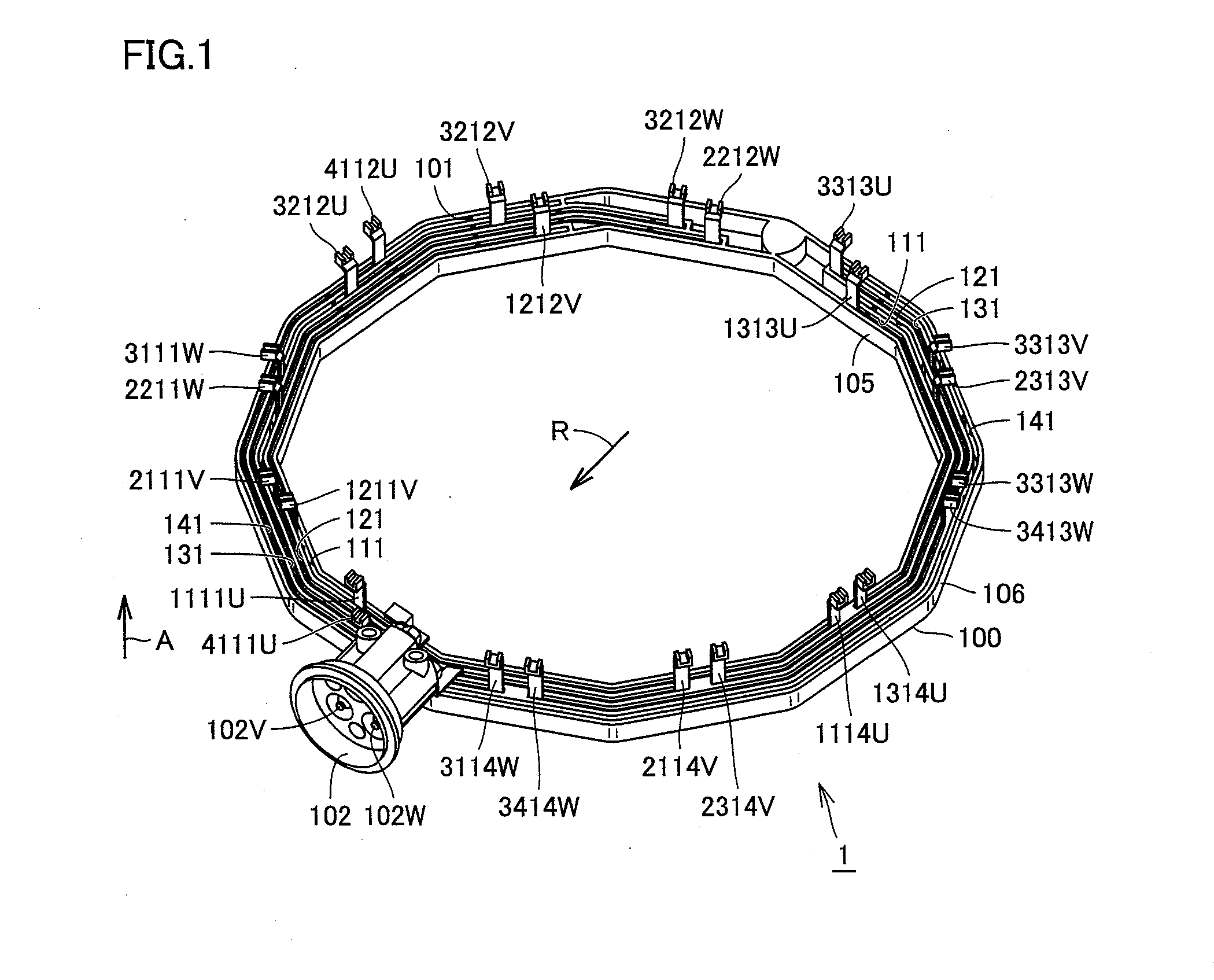
[0030]FIG. 1 is a perspective view of a terminal module for a rotating electric machine according to the present invention. Referring to FIG. 1, a terminal module 1 for a rotating electric machine includes a rail 100. Rail 100 takes a ring (annular) shape of a regular dodecagon, formed to surround a predetermined space. The shape of rail 100 is not limited to a dodecagon, and may take any other polygonal shape. The shape of rail 100 is determined based on the number of cassette coils arranged in rail 100.

[0031]Rail 100 includes an inner circumferential face 105 and an outer circumferential face 106. Both of inner and outer circumferential faces 105 and 106 are flat. Inner circumferential face 105 and outer circumferential face 106 are lo...


PUM


Abstract

A terminal module for a rotating electric machine, allowing automatic assembling, is provided. The terminal module for a rotating electric machine includes a polygonal rail (100) provided with a groove, and a polygonal bus bar fitted in the groove.

Description

TECHNICAL FIELD[0001]The present invention relates to a terminal module for a rotating electric machine, and a rotating electric machine. More particularly, the present invention relates to a terminal module for a rotating electric machine having a cassette coil of concentrated winding attached, and a rotating electric machine utilizing the same.BACKGROUND ART[0002]Conventional rotating electric machines are disclosed in, for example, Japanese Patent Laying-Open Nos. 2003-284279 (Patent Document 1), 2004-242472 (Patent Document 2), and 9-322459 (Patent Document 3).DISCLOSURE OF THE INVENTION[0003]Patent Document 1 discloses a collecting / distributing ring having three bus bars integrated in annular form, bundling external connection terminals.[0004]Patent Document 2 discloses a conductive path having bus bars with electric line terminals molded with resin, facilitating connection of the electric wires of a motor. In addition, integration of the connector for the electric wires is tau...

Claims


Application Information

Patent Timeline
Patent Type & Authority Applications(United States)
IPC IPC(8): H02K11/00
CPCH02K3/522H02K2203/12H02K2203/09H02K5/225
Inventor TSUKASHIMA, HIROYUKIMIYAZAKI, SHO
Owner TOYOTA JIDOSHA KK
Why Eureka
Try Eureka