
Door supporting device for refrigerator

Active Publication Date: 2009-02-12
LG ELECTRONICS INC
View PDF10 Cites 39 Cited by
  • Summary
  • Abstract
  • Description
  • Claims
  • Application Information

AI Technical Summary

Benefits of technology

[0022]According to the present invention described above, it can be expected to obtain the following advantages.
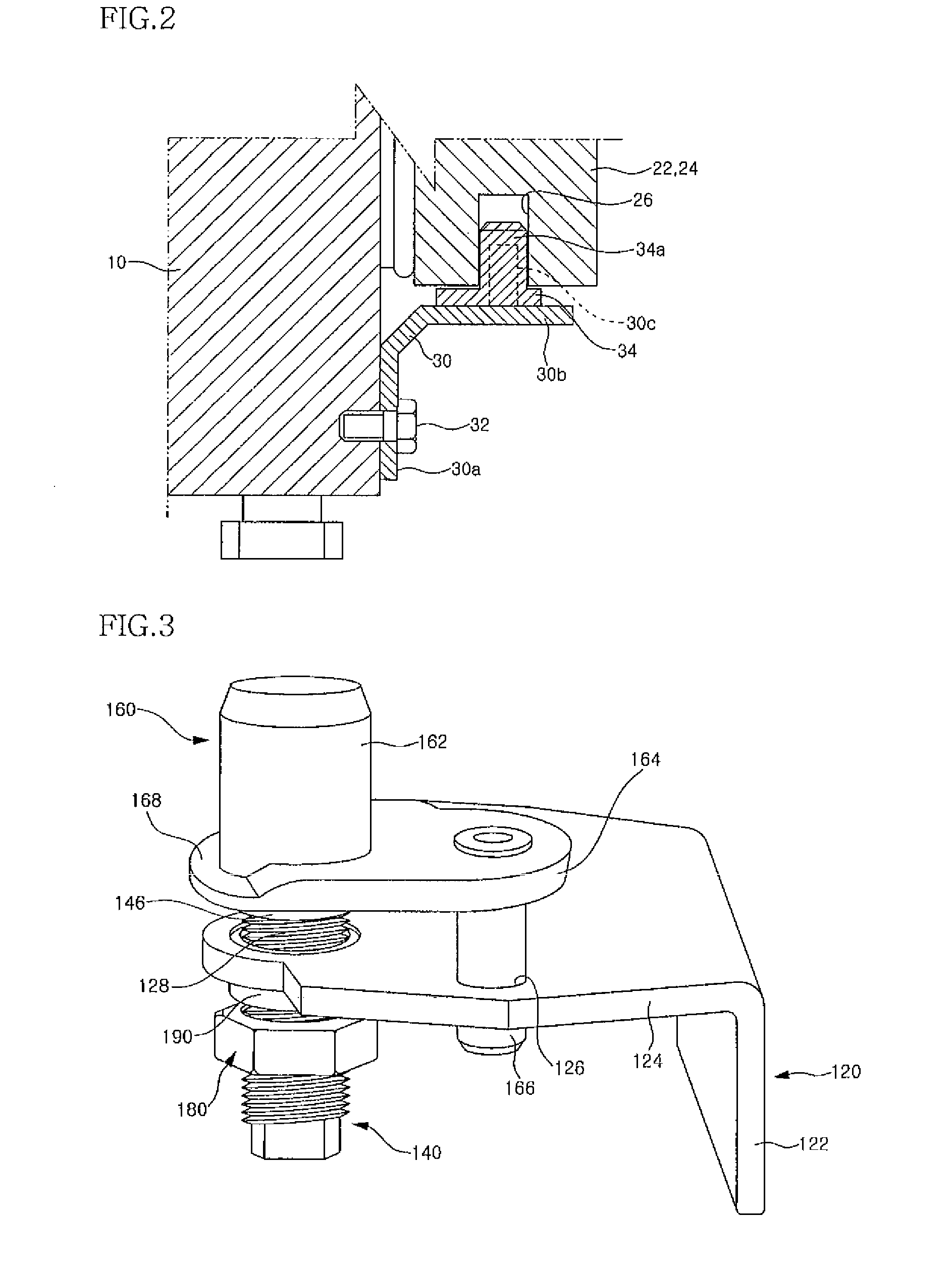
[0023]First, it is possible to adjust the height of a door by rotating the hinge shaft 140. Therefore, it is possible to adjust the height of the door even in a state where the door is mounted on a main body of a refrigerator. Particularly, in a side-by-side type refrigerator, the heights of doors of the refrigerator which are installed side by side can be adjusted to be at the same level.
[0024]Further, according to the present invention, it can be understood that the hinge cap is constructed not to be rotated and the nut is engaged with the lower portion of the hinge shaft 140 so that the rotation of the hinge shaft 140 caused by external forces can be substantially prevented. With such a structure, the hinge shaft is not rotated by an external force. Thus, the door can be maintained at a predetermined height as it is, resulting in improved reliability of a product.

Problems solved by technology

In the conventional refrigerator thus constructed, there is a disadvantage in that the freezing chamber door 24 and the refrigerating chamber door 22 may not be horizontally disposed at the same level due to assembly tolerance between the main body and the doors when they are assembled with each other, or either one of the doors 22 and 24 may be sagged downwardly due to fatigue loads resulting from repeated opening and closing of the doors by a user for a long period of time.
However, as described above, there are problems in that the case where the both doors are not horizontally disposed at the same level due to the assembly tolerance in an assembling process may occur, and the doors 22 and 24 may not be maintained in the horizontal state but sagged due to the weights of the doors and fatigue loads resulting from the repeated opening and closing of the doors during the use thereof for a long period of time, thereby causing variation in their heights.

Method used


Image

  • Door supporting device for refrigerator
  • Door supporting device for refrigerator
  • Door supporting device for refrigerator

Examples


Embodiment Construction

[0049]Next, another embodiment of the present invention shown in FIG. 6 will be described. In this embodiment, components identical with those of the previous embodiment will be designated by identical reference numerals, and descriptions overlapping with those of the previous embodiment will be omitted. This embodiment is configured to improve convenience in machining a hinge bracket.

[0050]As shown in the figure, a hinge bracket 120 comprises a fixing portion 122 fixed to a lower end of a front surface of a refrigerator, and a supporting portion 124 extending forward from an upper end of the fixing portion 122 in a horizontal direction. The supporting portion 124 is formed with a fixing hole 126 into which a rotation preventing projection 166 of a hinge cap 160 is inserted. Further, a supporting hole 128a into which a socket 190a to be described later is to be fixedly inserted is formed at a front side with respect to the fixing hole 126 of the supporting portion 124. In this embod...


PUM


Abstract

The present invention relates to a door supporting device for a refrigerator. The door supporting device of the present invention can adjust the height of the door. A hinge bracket of the door supporting device of the present invention includes a fixing portion fixed to a front face of the refrigerator, and a supporting portion extending forward from an upper end of the fixing portion and having a threaded hole with threads formed on an inner periphery thereof. A hinge shaft of the door supporting device has threads on an outer periphery thereof and is threadly engaged with the threaded hole so that the hinge shaft can be supported by the hinge bracket. An upper end of the hinge shaft rotatably supports the door. The height of the door can be adjusted by rotating the hinge shaft. A nut is threadly engaged with the hinge shaft below the hinge bracket. The nut prevents the hinge shaft from being rotated so that the door can be constantly maintained at a predetermined height. The door supporting device further comprises a hinge cap fitted around the upper end of the hinge shaft and inserted into a hinge hole formed in a bottom surface of the door so as to rotatably support the door. The hinge cap comprises a rearward extension and a rotation preventing projection extending downward from the extension, and the rotation preventing projection is inserted into a fixing hole of the hinge bracket so as to restrict rotation of the hinge cap.

Description

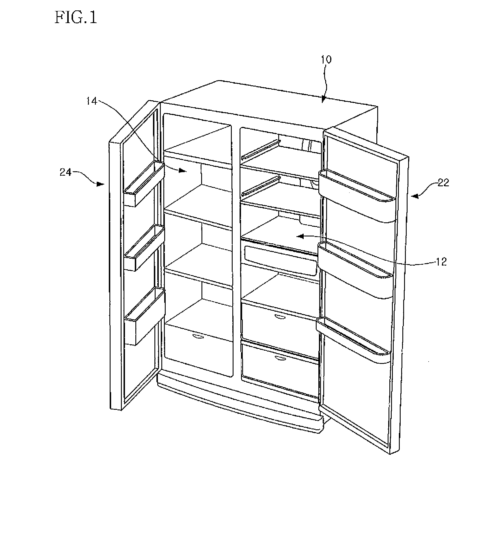
TECHNICAL FIELD[0001]The present invention relates to a refrigerator having a height-adjustable door, and more particularly, to a refrigerator having a height-adjustable door, which is constructed such that the height of the door can be easily adjusted and the door can also be supported without any change in its height even though it is used for a long period of time.BACKGROUND ART[0002]FIG. 1 is a perspective view showing the structure of a typical side-by-side type refrigerator, and FIG. 2 is a sectional view illustrating a supporting structure for a door of a conventional refrigerator. As shown in FIG. 1, a main body 10 of the typical refrigerator has a refrigerating chamber 12 and a freezing chamber 14, which have open front faces, as storage spaces to store foodstuffs in a refrigerated state and a frozen state, respectively.[0003]Further, the open front faces of the refrigerating chamber 12 and the freezing chamber 14 are opened and closed by a refrigerating chamber door 22 and...

Claims


Application Information

Patent Timeline
IPC IPC(8): F25D23/02
CPCE05D7/0027E05Y2600/00E05Y2900/31F25D23/028Y10T16/53235E05Y2800/40E05D7/081Y10T16/533Y10T16/53225F25D2323/024F25D23/02F25D23/00
Inventor MOON, SUN-NAM
Owner LG ELECTRONICS INC
Learn More