
Travel speed limitting apparatus

a technology of limiting apparatus and travel speed, which is applied in the direction of brake systems, process and machine control, instruments, etc., can solve the problems of large deviation of inability to keep the target ap opening, etc., and achieve the effect of preventing an operator from feeling discomfort and rapid reducing the travel speed

Inactive Publication Date: 2009-02-05
HONDA MOTOR CO LTD
View PDF2 Cites 6 Cited by
  • Summary
  • Abstract
  • Description
  • Claims
  • Application Information

AI Technical Summary

Benefits of technology

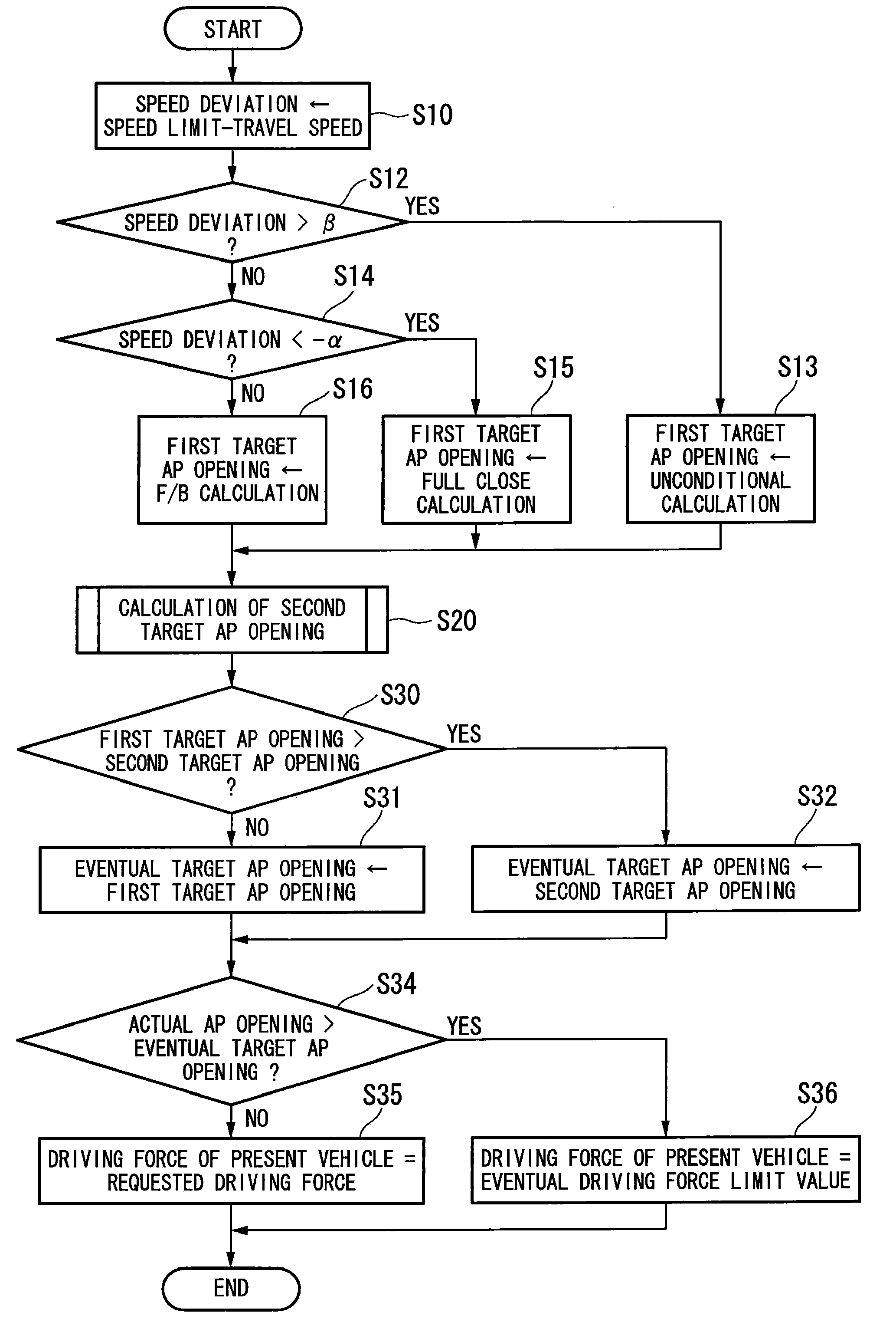
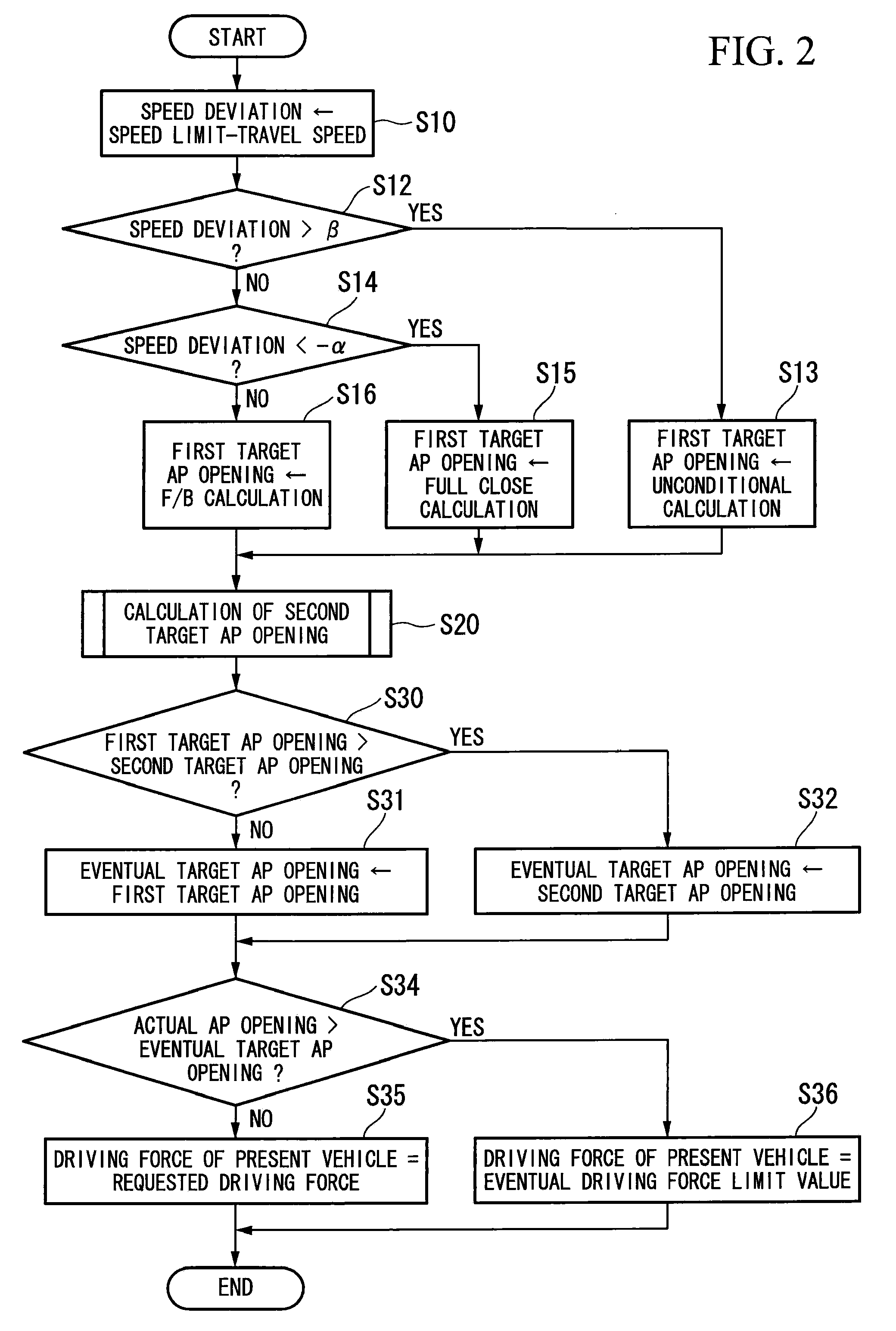
[0014]According to the above-described travel speed limiting apparatus, since the second driving force limit value is calculated based on the requested driving force and the eventual driving force limit value is set to the smaller of the first driving force limit value and the second driving force limit value, the correction value based on the speed deviation can be prevented from being accumulated even in the case where the travel speed is kept less than the speed limit. As a result, a significant excess of the eventual driving force limit value can be avoided. Besides that, since the driving force of the present vehicle is controlled so as to be less than the eventual driving force limit value, an acceleration of the present vehicle can be suppressed even in the case where the acceleration pedal is depressed. As a result, the travel speed can be prevented from significantly exceeding the speed limit.
[0017]In these cases, since the eventual driving force limit value does not significantly excess the requested driving force, a significant increase of the first driving force limit value that is calculated on the basis of the eventual driving force limit value can be avoided. For this reason, the driving force of the present vehicle can be controlled so as to be less than the first driving force limit value by reducing the first driving force limit value immediately to the appropriate value even in the case where the acceleration pedal is depressed.
[0020]In these cases, since the variation of the second drive force limit value calculated based on the requested driving force is controlled so as to be less than a predetermined value, the second drive force limit value can be less than the requested driving force in the case where the requested driving force rapidly increases. Therefore, the acceleration of the present vehicle can be suppressed. As a result, the travel speed can be prevented from significantly exceeding the speed limit.
[0023]In these cases, since the variation of the second drive force limit value calculated based on the requested driving force is controlled so as to be less than a predetermined value only when the variation is a positive value, it is possible to reduce the second drive force limit value along with the requested driving force in the case where the requested driving force rapidly decreases. Therefore, the travel speed can be rapidly reduced. As a result, it is possible to prevent an operator from feeling discomfort.

Problems solved by technology

As a result, there is a problem in that the travel speed exceeds the speed limit to a large degree because of the excess acceleration of the present vehicle.
However, because of the feed-back control based on the speed deviation, the decrease of the target AP opening does not keep up with the increase of the travel speed, and thereby the travel speed is kept greater than 100 km / h (overshoot) for a while.

Method used


Image

  • Travel speed limitting apparatus
  • Travel speed limitting apparatus
  • Travel speed limitting apparatus

Examples


Embodiment Construction

[0029]An embodiment of the present invention is explained below with reference to the drawings.

(Travel Speed Limiting Apparatus)

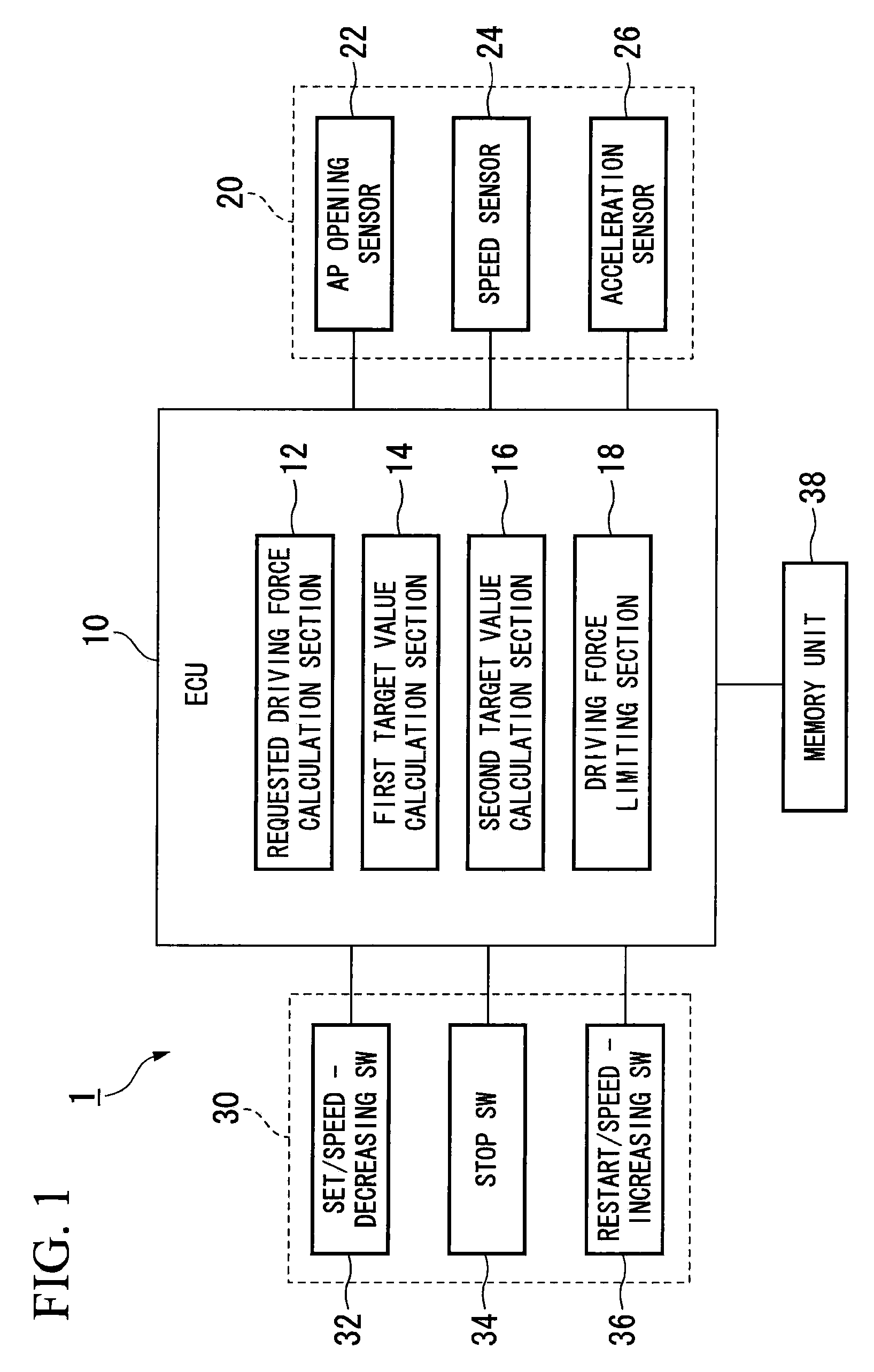
[0030]FIG. 1 is a block diagram of a travel speed limiting apparatus according to the present embodiment. The travel speed limiting apparatus 1 includes a vehicle status sensor 20, a speed limit set switch 30, and ECU 10 which calculates a target AP opening and the like. The AP opening sensor 10 includes an AP opening sensor 22 which detects an acceleration pedal opening (hereinafter referred to as an AP opening), a speed sensor 24 (travel speed measurement device), and an acceleration sensor 26 which measures an acceleration of the present vehicle.

[0031]The speed limit set switch 30 includes a set / speed-decreasing switch 32, a stop switch 34, and a restart / speed-increasing switch 36. In setting the speed limit, first, the set switch 32 is pressed to display a value of the speed limit on an instrument panel or the like mounted on the present vehicle. The sp...


PUM


Abstract

A travel speed limiting apparatus including: a travel speed measurement device which measures a travel speed of a vehicle; a speed limit memory device which stores a speed limit set by an operator; a first driving force limit value calculation device which calculates a first driving force limit value based on a deviation of the travel speed from the speed limit; a requested driving force calculation device which calculates a requested driving force based on an operator's acceleration operation; and a second driving force limit value calculation device which calculates a second driving force limit value based on the requested driving force, wherein the driving force limiting device sets an eventual driving force limit value to the smaller of the first driving force limit value and the second driving force limit value, and controls the driving force of the vehicle to be less than the eventual driving force limit value.

Description

BACKGROUND OF THE INVENTION[0001]Priority is claimed on Japanese Patent Application No. 2007-202947, filed Aug. 3, 2007, the content of which is incorporated herein by reference.FIELD OF THE INVENTION[0002]The present invention is related to a travel speed limiting apparatus for a vehicle.DESCRIPTION OF THE RELATED ART[0003]A travel speed limiting apparatus (variable speed limiter) controlling a speed of a present vehicle so as not to exceed a driver's predetermined speed is known (see, for example, Japanese Unexamined Patent Application, First Publication No. H11-294215).[0004]FIGS. 5A and 5B are graphs showing the relationship between an accelerator pedal opening and travel speed according to the conventional technology. In the conventional travel speed limiting apparatus, a target accelerator pedal opening (hereinafter referred to as an AP opening), as shown in FIG. 5B, is calculated so that the speed deviation (speed limit Vm—travel speed), as shown in FIG. 5A, becomes zero.[000...

Claims


Application Information

Patent Timeline
Patent Type & Authority Applications(United States)
IPC IPC(8): B60T8/32
CPCB60K31/00B60W2520/10B60W2710/105B60W2540/10B60W2520/105B60W30/146
Inventor SEN, NAOTOSATO, HIROSHIOKADA, TADAYOSHINISHIDA, KENICHITOMOKUNI, YASUHIKONAKAHAMA, HIDEO
Owner HONDA MOTOR CO LTD
Learn More