
Flat-panel TV wall support with adjustable visual angle

a technology of visual angle and tv, which is applied in the direction of machine supports, instruments, cabinet/cabinet/drawer, etc., can solve the problems of insufficient flexibility, inability to meet directions and heights, and inability to watch from different distances, etc., to achieve flexible tv movement, increase the utilization rate of space, and increase the displacement distance

Inactive Publication Date: 2009-02-05
LE JIANRONG
View PDF4 Cites 31 Cited by
  • Summary
  • Abstract
  • Description
  • Claims
  • Application Information

AI Technical Summary

Benefits of technology

[0003]The technical problem to be settled is to provide a Flat-Panel TV Wall Support with reasonable structure, convenient installation, large TV adjusting angle, higher flexibility and adjustable visual angle.
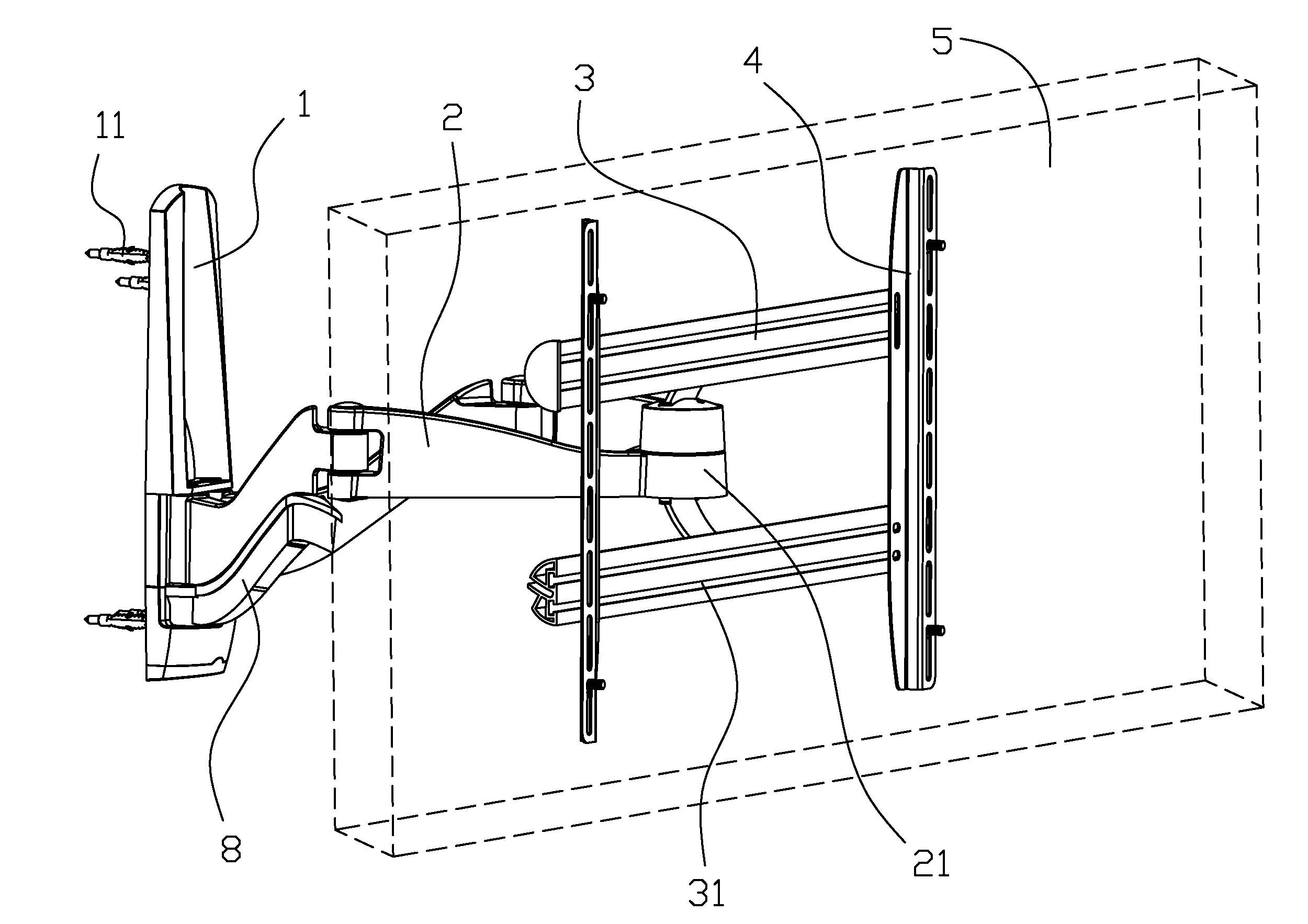
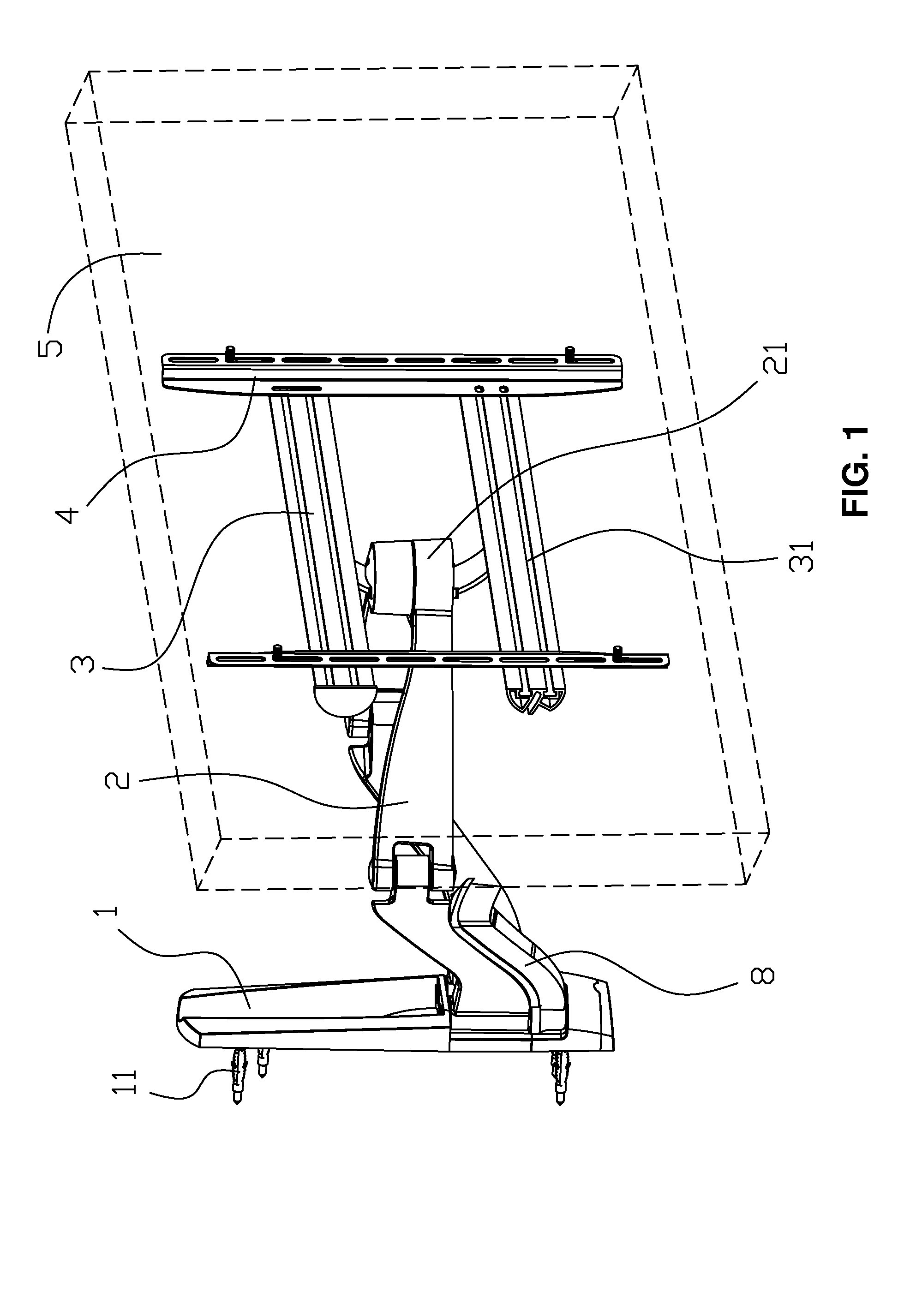
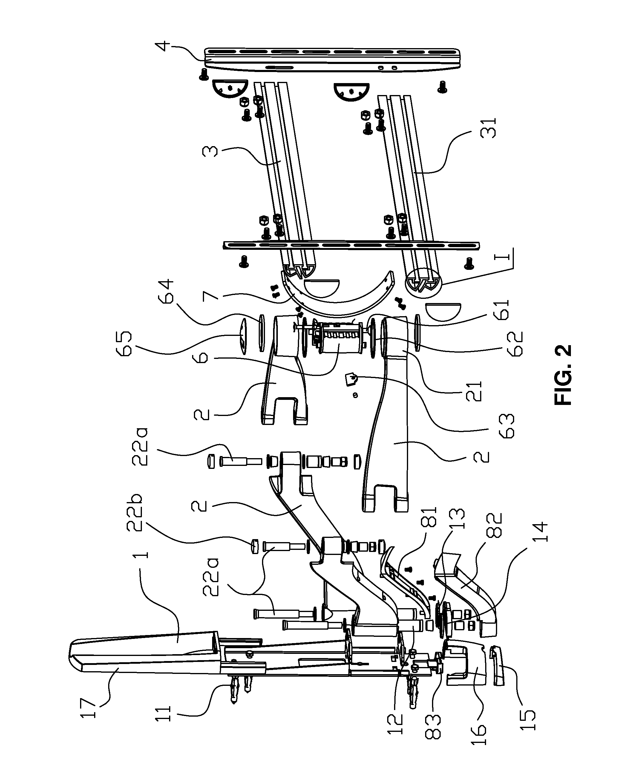
[0007]As a further improvement, the TV fixing mechanism comprises hanging bars and hanging plates, wherein the hanging bars are transversely arranged at the upper and lower positions and parallel to each other, the hanging plates are perpendicular to the hanging bars and parallel to each other, the hanging bars are connected with the hanging plates by bolts and screws, and the hanging bars is connected with the rotational component through the connecting plate, the flat panel TV is arranged on the hanging plate. Preferably, the number of the hanging bars are two, and the number of the hanging plates are also two, the two hanging bars are connected with the two hanging plates in “#” shape, wherein each hanging bar is provided with T-shape grooves which can adjust the transversal position of the hanging plates on hanging bar and make installation easier, while each hanging plate is designed as folded plate which can make installation easier and safer.
[0011]Compared with prior art, the present invention adopt four movable arms to form a four bar linkage mechanism with mutual linkage capability and parallelogram top view projection, wherein the front end of the four bar linkage mechanism is movably connected with the TV fixing mechanism, while the tail end of the four bar linkage mechanism is movably connected with the wall installing board. This design has advantages of that: the parallelogram four bar linkage mechanism makes the movement of TV more flexible as well as provides larger displacement distance; The rear ends of the four bar linkage mechanism is mainly converged at a certain point, therefore the installation area of wall surface is small, and so is the covering space. For example, when the TV is moved to left by four bar linkage mechanism, the right space will be vacated, and vice versa, therefore the utilization rate of space becomes higher; in addition, the present TV fixing mechanism only comprises two hanging bars, two hanging plates and one rotational component, therefore this mechanism has extremely simple structure, ingenious application principle and better practicality.

Problems solved by technology

Therefore, the need of watching from different distances, directions and heights can not be satisfied; in addition, most traditional installing structures are splicing of reinforcing rods, wherein the installation steps are rather complicated.
But this product also has the following disadvantages: the front and rear ends of inner and outer swinging arms do not converge at a certain point but are installed separately, therefore not only the covering space is lager but also the left and right shift distances are limited, besides, the left and right turning angles are also limited, thus the flexibility is insufficient; in addition, the design is really complicated, the quantity of manufacture parts is large, and the assembly during installation is difficult, that is, the structure is neither reasonable nor simple, therefore the product should be further improved.

Method used


Image

  • Flat-panel TV wall support with adjustable visual angle
  • Flat-panel TV wall support with adjustable visual angle
  • Flat-panel TV wall support with adjustable visual angle

Examples


Embodiment Construction

[0019]The detailed description of the present invention is followed in conjunction with the figures.

[0020]FIG. 1 to 7 shows that the Flat-Panel TV Wall Support with adjustable visual angle of the present invention, comprises a wall installing board 1, a TV fixing mechanism and an adjusting mechanism for adjusting the position of the TV fixing mechanism; wherein, the TV fixing mechanism is connected with the wall installing board 1 through the adjusting mechanism. The adjusting mechanism comprises four movable arms 2, which forms a four bar linkage mechanism with mutual linkage capability and parallelogram top view projection, wherein the front end 21 of the four bar linkage mechanism is movably connected with the TV fixing mechanism, while the tail end 22 of the four bar linkage mechanism is movably connected with the wall installing board 1. The tail ends 22 of the two movable arms 2 in rear are located in a same plane and swing arranged on the wall installing board 1 side by side ...


PUM


Abstract

A Flat-Panel TV Wall Support with adjustable visual angle, comprising a wall installing board, a TV fixing mechanism and an adjusting mechanism for adjusting the location of TV fixing mechanism; the TV fixing mechanism is connected with the wall installing board through the adjusting mechanism, wherein the adjusting mechanism comprises four movable arms, which forms a four bar linkage mechanism with mutual linkage capability and parallelogram top view projection, wherein the front end of the four bar linkage mechanism is movably connected with the TV fixing mechanism, while the tail end of the four bar linkage mechanism is movably connected with the wall installing board. Compared with prior art, the present invention has advantages of that: the four bar linkage mechanism makes the movement of TV more flexible, and needs less installation area. In addition, the TV fixing mechanism has extremely simple structure, ingenious application principle and better practicality.

Description

FIELD OF THE INVENTION[0001]The present invention relates to a wall mounting mechanism used in plasma and LCD flat panel TVs, and more particularly to a Flat-Panel TV Wall Support with adjustable visual angle over a large range for different viewing distances, plane swing angle and tilt angle of screen.BACKGROUND OF THE INVENTION[0002]With the rapid development of science and technology, plasma and LCD flat panel TVs are replacing traditional cathode ray tube TVs and entering common families. These new TVs are also used in information transmission and image projection for public places such as enterprises and institutions, hospital, stock exchange, station, wharf, airport and various transportation means. At present, the main installation methods of plasma and LCD flat panel TVs are supporting with chassis and hanging, and the viewing distance, plane swing angle and tilt angle of screen of most installed TVs can not be adjusted or only one of above functions can be adjusted. Therefo...

Claims


Application Information

Patent Timeline
Patent Type & Authority Applications(United States)
IPC IPC(8): G06F1/16
CPCF16M11/04F16M11/045F16M11/2064F16M2200/065F16M13/02F16M2200/061F16M11/2092
Inventor LE, JIANRONG
Owner LE JIANRONG
Learn More