
Orthosis Apparatus and Method of Using an Orthosis Apparatus

a technology of orthosis and orthosis, applied in the field of orthosis, can solve the problems of causing the damage of the ankle joint, and affecting the movement of the joint,

Active Publication Date: 2009-01-29
BONUTTI RES
View PDF99 Cites 77 Cited by
  • Summary
  • Abstract
  • Description
  • Claims
  • Application Information

AI Technical Summary

Benefits of technology

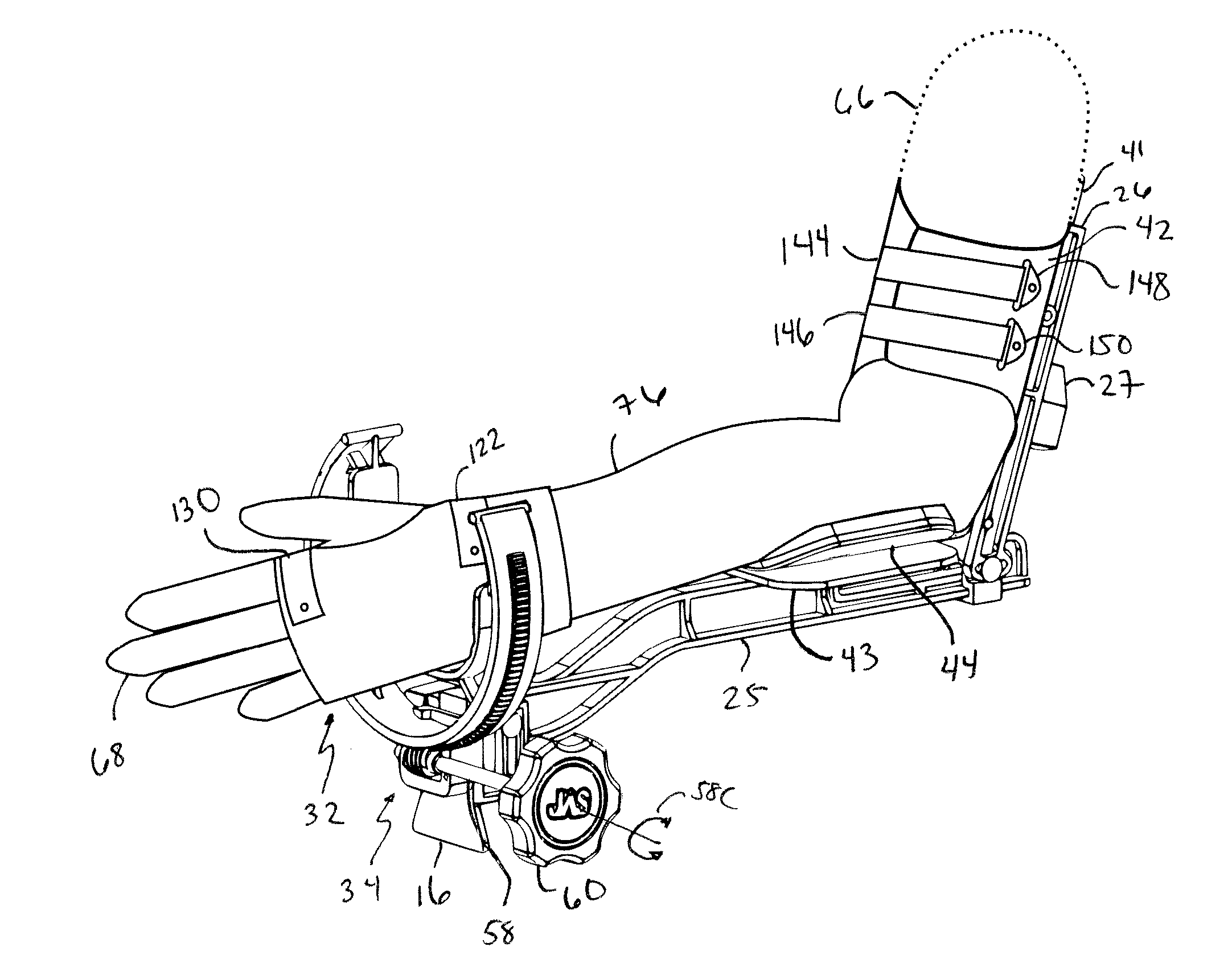
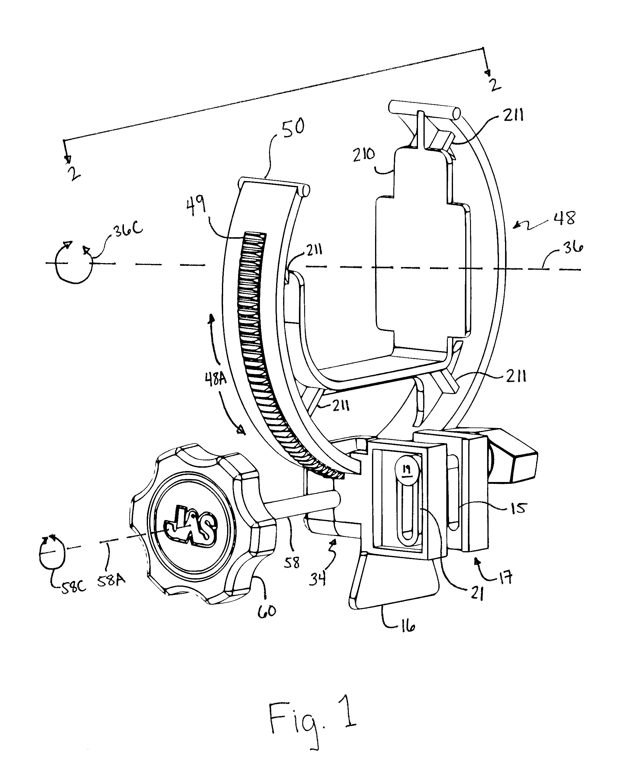
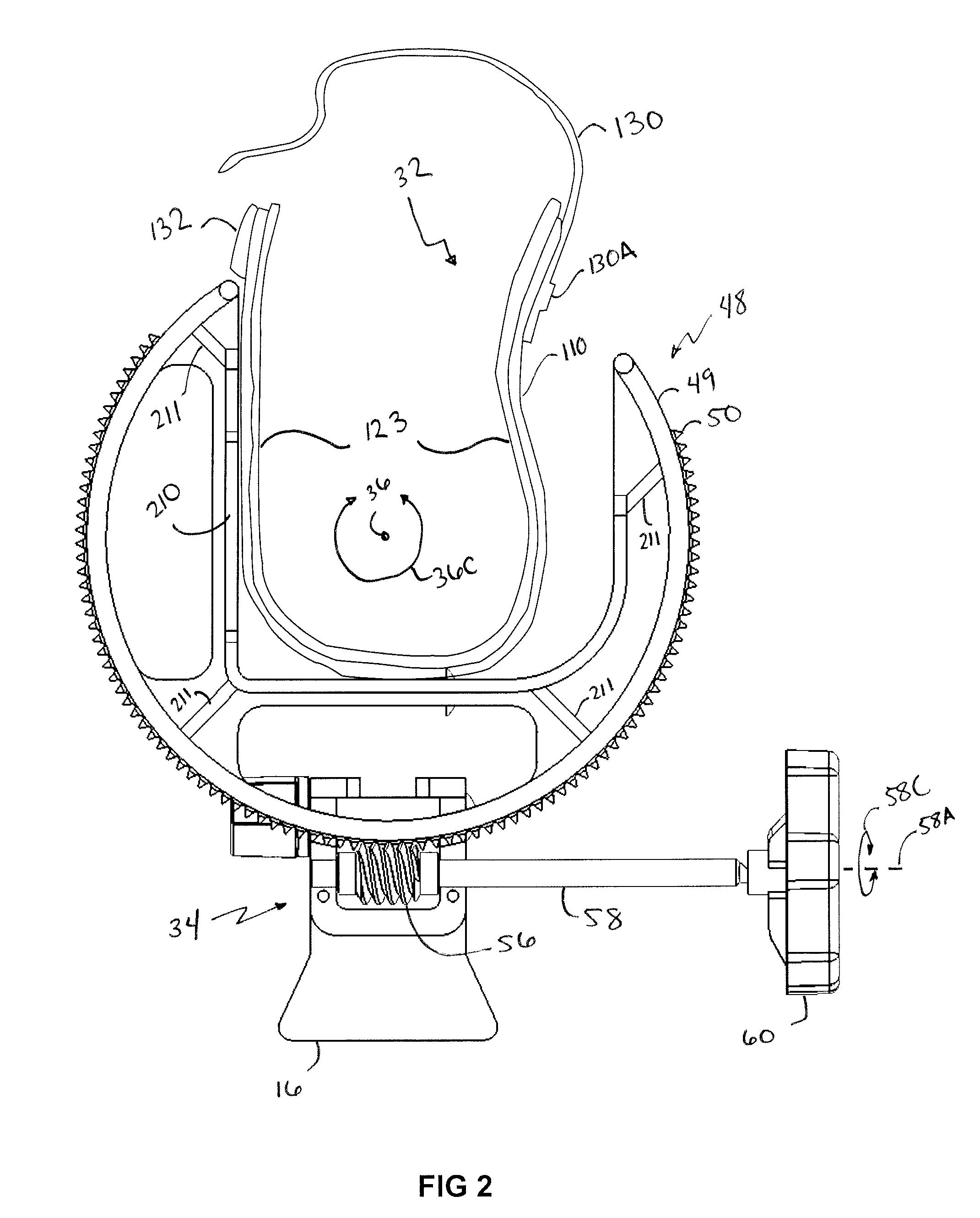
[0008]What is disclosed is a new and improved method and apparatus for use in effecting relative movement between a patient's hand and the bones in the patient's arm. The novel apparatus includes a main gear assembly having a lower cuff affixed therethrough for gripping a wrist and hand. The lower cuff can secure to a distal bone (i.e. the hand) and a medial bone (i.e. the forearm) of an appendage of a patient. The lower cuff centers the longitudinal axis of the forearm during rotational distal adjustment. The main drive assembly rotatable varies the extent of pronation and / or supination of the hand of the patient. A lower cuff arm connects, on one end, a vertical adjustment portion integral to the main gear assembly. The longitudinal axis of the patient's forearm is coincident with the longitudinal axis of the lower cuff arm. The lower cuff arm has a center cuff affixed on the lower cuff. The patient's arm rests on the center cuff during the use of the apparatus. The lower cuff arm is vertically adjustable relative to the fixed position of the rotatable drive assembly gripping the patient's hand. An adjustable upper cuff arm slideably attaches to an opposite end of the lower cuff arm at a point located behind the center cuff for gripping the patient's upper arm and holding it in a fixed position relative to the rotation of the hand. An upper cuff arm is adjustable both along the center axis of the lower cuff arm and along an angle of declination formed between the patient's upper arm and the lower cuff arm. The declination of the forearm relative to the upper arm is preferably adjustable and can be securely fixed at a desired angle by the medical practitioner to achieve the desired therapeutic effect. The interchangeability of the different parts of the orthosis of the present invention effectuates the device's assembly / disassembly and the interchangeability of parts to meet the patient's therapeutic needs.

Problems solved by technology

Extension of the ankle would damage that joint.
When a joint is injured either by trauma or by surgery, scar tissue can form, often resulting in flexion or extension contractures which can adversely affect the movement of the joint.

Method used


Image

  • Orthosis Apparatus and Method of Using an Orthosis Apparatus
  • Orthosis Apparatus and Method of Using an Orthosis Apparatus
  • Orthosis Apparatus and Method of Using an Orthosis Apparatus

Examples


Embodiment Construction

[0049]Briefly, what is disclosed is a new and improved method and apparatus for use in effecting relative movement between a patient's hand and the bones in the patient's arm. The novel apparatus includes a main gear assembly having a lower cuff affixed there through for gripping a wrist and hand. The lower cuff centers the longitudinal axis of the forearm during rotational distal adjustment. The main drive assembly rotatably varies the extent of pronation and / or supination of the hand of the patient. A lower cuff arm connects, on one end, a vertical adjustment portion integral to the main gear assembly. The longitudinal axis of the patient's forearm coincident with the longitudinal axis of the lower cuff arm. The lower cuff arm has a center cuff affixed thereon upon which the patient's arm rests during the use of the present apparatus. The lower cuff arm is vertically adjustable relative to the fixed position of the rotatable drive assembly gripping the patient's hand. An upper cuf...


PUM


Abstract

The present invention provides a new and improved orthosis for use in effecting relative movement between bones in an arm of a patient. The apparatus includes a lower cuff gripping distal bone, such as a wrist, and an upper cuff gripping a proximal bone, such as an upper arm. The lower cuff is secured in a rotatable drive assembly substantially coincident to a longitudinal axis of a medial bone, such as the forearm, during rotational distal adjustment. The angle between the forearm and the upper arm is adjustable and can be securely fixed at a desired angle. The rotation of the rotatable drive assembly effectuates the pronation and supination of the hand and wrist relative to the patient's forearm. The orthosis of the present invention can be disassembled with interchanging parts substituted depending on the patient's needs.

Description

CROSS REFERENCE TO RELATED APPLICATIONS[0001]This application claims the benefit of U.S. Provisional Application No. 60 / 951,726, filed Jul. 25, 2007, and U.S. Provisional Application No. 61 / 033,786, filed Mar. 4, 2008. Both of the applications are incorporated by reference.FIELD OF THE INVENTION[0002]The present invention generally relates to orthoses for securing and rotating a human wrist and, more particularly, to an adjustable orthosis which can be used for stretching human tissue such as ligaments, tendons or muscles around a wrist and elbow joint.BACKGROUND OF THE INVENTION[0003]In a joint, the range of motion depends upon the anatomy of that joint and on the particular genetics of each individual. Typically, joints move in two directions, flexion and extension. Flexion is to bend the joint and extension is to straighten the joint; however, in the orthopedic convention some joints only flex. For example, the ankle has dorsiflexion and plantarflexion. Extension of the ankle wou...

Claims


Application Information

Patent Timeline
IPC IPC(8): A61H1/02A61F5/00
CPCA61F5/013A61H2201/165A61H1/0274A61F5/04
Inventor BONUTTI, PETER M.BONUTTI, BORIS P.RUHOLL, KEVIN R.PHILLIPS, GLEN A.
Owner BONUTTI RES
Learn More