
3-D visualization

a multi-dimensional data volume and visualization technology, applied in the field of 3-d visualization, can solve the problems of difficult orientation of the viewed portions of a 3-d, further limitation of the ability of the user to focus, and the continued handling and/or display of 3-d data volumes, so as to achieve the effect of enhancing the ability to visualiz

Inactive Publication Date: 2009-01-29
FUGRO JASON
View PDF33 Cites 51 Cited by
  • Summary
  • Abstract
  • Description
  • Claims
  • Application Information

AI Technical Summary

Benefits of technology

[0006]The following examples dispense with the need to produce 3-D volume subsets and the need to display such subsets along with portions of the original 3-D data volume in order to maintain a user's viewing orientation within the data volume, although the invention is not limited to systems and processes that make no such production or display. In at least one example, the user is presented with selected slices extracted from a 3-D data volume, which will be, in at least one example, translated or rotated in unison. Therefore, the user is provided with an enhanced ability to visualize, identify, and track features of interest. Further, more specific examples provide additional display of the pertinent areas of interest surrounding the feature while avoiding the need to display non-pertinent portions of a data volume.
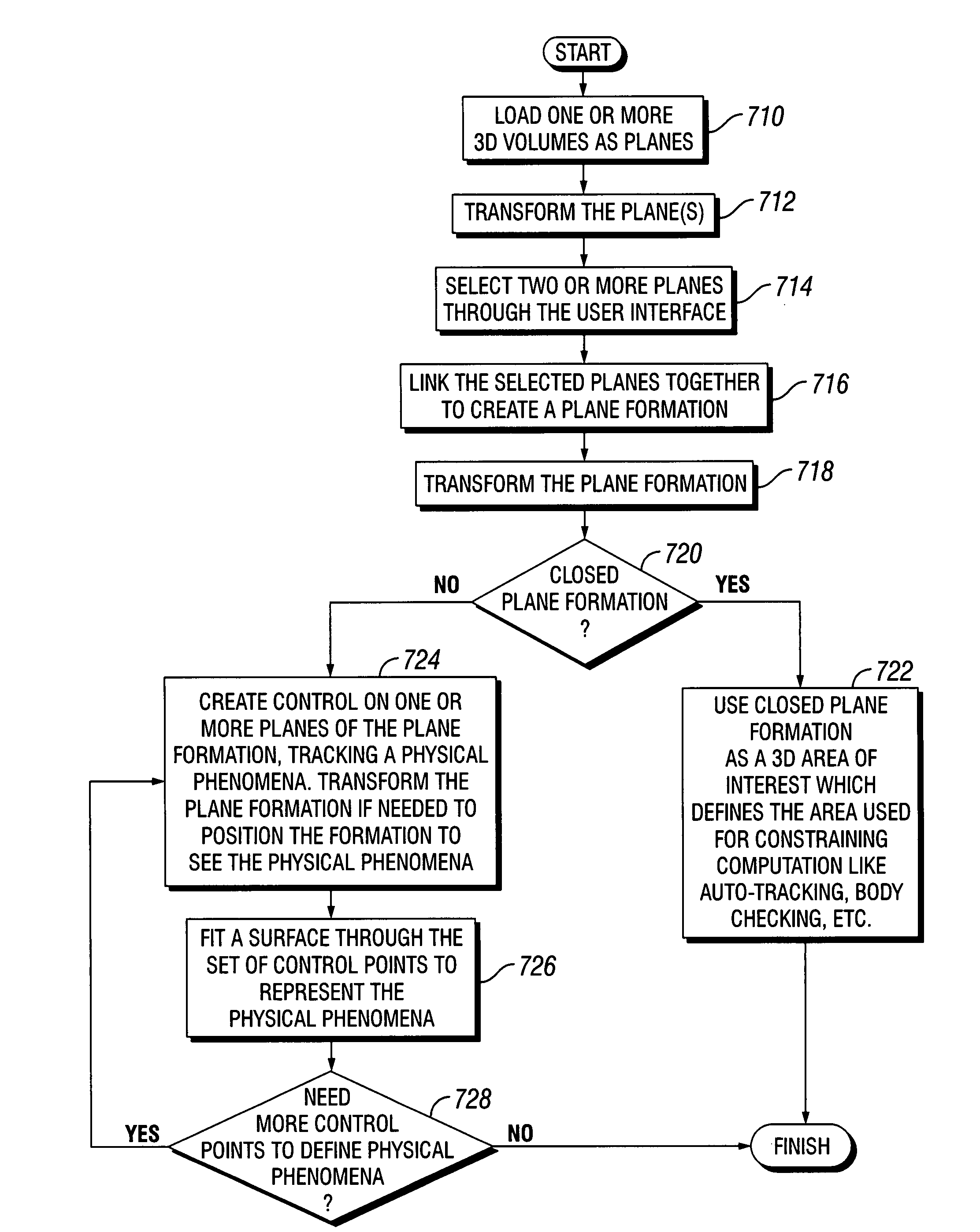
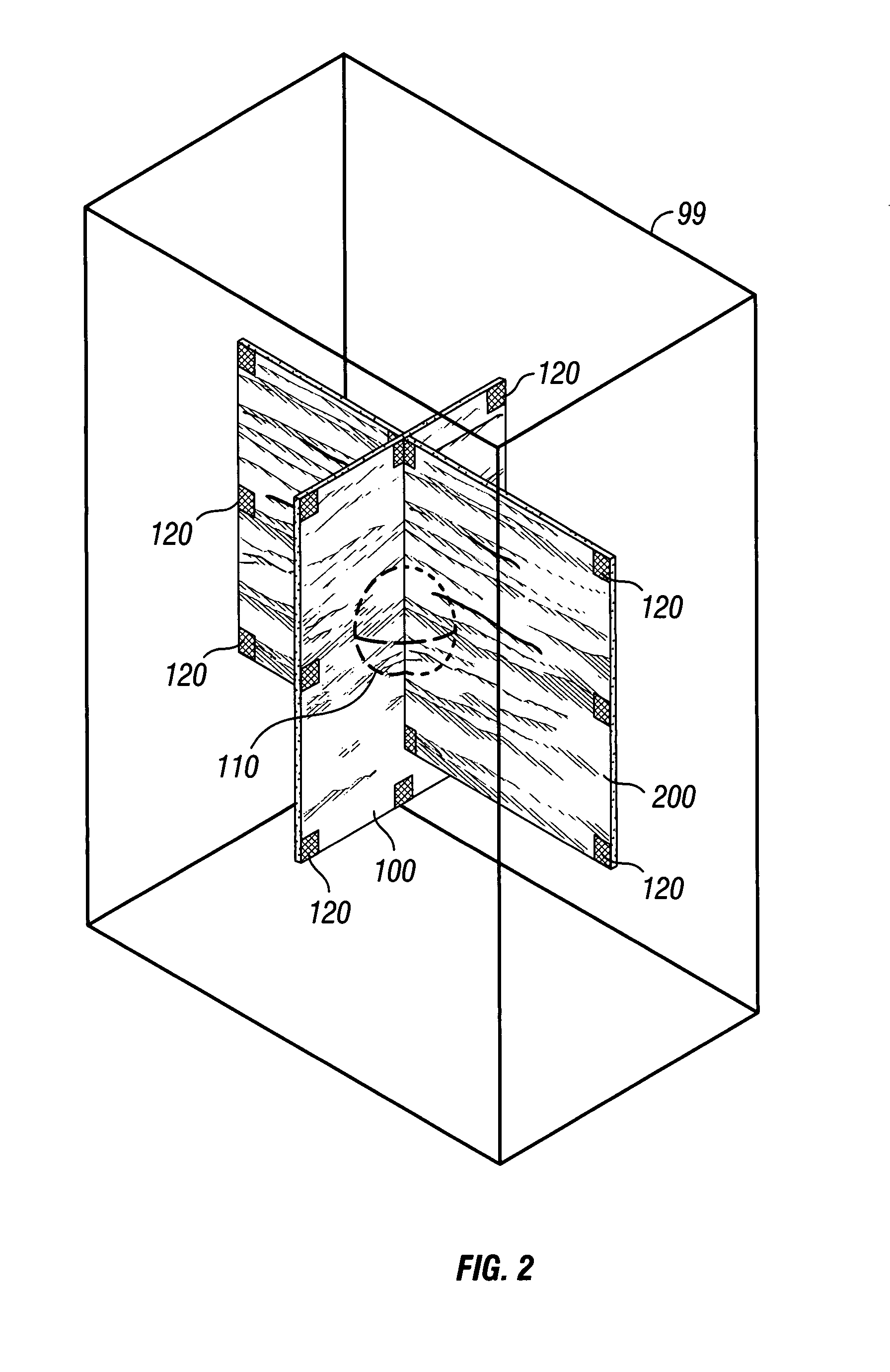
[0024]According to a second set of examples of the invention, a method for visualization of a multi-dimensional data volume is provided, representing a spatial zone for visualization and interpretation of physical parameters of the spatial zone selected by a user, the multi-dimensional volume being defined by one or more attributes and information leading to the placement of the attributes in the spatial zone, the method including: creating a plurality of 2-D parametric surfaces, where each 2-D parametric surface is derived from the data volume; drawing at least a portion of an image of each 2-D parametric surface for display to a user; linking at least two of the plurality of 2-D parametric surfaces to each other; performing an operation on the linked at least two of the plurality of 2-D parametric surfaces while maintaining the relative orientation of the at least two of the plurality of 2-D parametric surfaces with respect to each other; and repeating the drawing step.

Problems solved by technology

Current practice renders it difficult to orient the viewed portions of a 3-D data volume so as to align and track the dip and strike viewing perspectives.
This renders the user further limited in ability to focus on identification and tracking of features across various combinations of angles of perspective within the data volume.
These techniques are limited by the continued handling and / or display of 3-D data volumes, either through continued display of a portion of the 3-D data volume and / or one or more subset data volumes.
This causes a number of problems.
This capacity is overwhelmed by such a visualization technique.

Method used


Image

  • 3-D visualization
  • 3-D visualization
  • 3-D visualization

Examples


Embodiment Construction

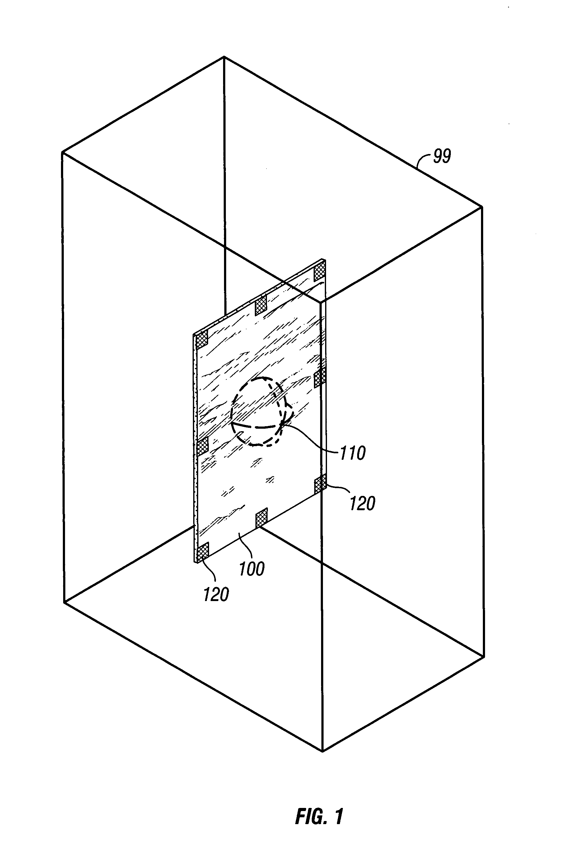
[0089]In some examples of the invention, 2-D parametric surfaces consist essentially of planar slices extracted or derived, thereby created, from a data volume. Alternatively, 2-D parametric surfaces consist essentially of surfaces having shape in two or three dimensions, while not having thickness of the surface. In either case, the 2-D parametric surfaces serve as visualization surfaces. Selected attribute values from a selected data volume are displayed upon these parametric surfaces by projecting the attribute values onto the parametric surfaces where the parametric surfaces intersect the selected data volume. In some examples, multiple attribute values from one or more data volumes are projected. In further examples, differing attributes or attribute sets are projected onto different parametric surfaces. In a further example, two or more 2-D parametric surfaces are linked for purposes of translation or rotation, in unison, within the data volume or data volumes. Such linking an...


PUM


Abstract

An apparatus, computer program, method, system, and graphical display are provided for analyzing and imaging 3-D or multi-dimensional data volumes using linked 2-D parametric surfaces. At least two 2-D parametric surfaces are each derived from a multi-dimensional data volume. The 2-D parametric surfaces are displayed. The 2-D parametric surfaces are linked to each other. A user interface enables rotation, translation, or scaling of the planes. The linked planes are operated upon in unison. The 2-D parametric surfaces are redisplayed. A subset area may be defined to restrain the area of additional computations.

Description

FIELD OF THE INVENTION[0001]The present invention relates to enhanced visualization of 3-D or multi-dimensional data volumes. More particularly, the present invention relates to enhanced visualization and identification of features contained within a multidimensional data volume.BACKGROUND TO THE INVENTION[0002]The visibility of geologic and / or topographic features in a 3-D data volume depends greatly on the viewing angle of perspective of the subject feature. A steep or faulted structure is most visible in its “dip” direction versus its perpendicular “strike” direction. The dip or strike direction of a feature may not be aligned to the axes of a 3-D data volume and furthermore may change along the lateral extent of the feature. Current practice renders it difficult to orient the viewed portions of a 3-D data volume so as to align and track the dip and strike viewing perspectives. This renders the user further limited in ability to focus on identification and tracking of features ac...

Claims


Application Information

Patent Timeline
Patent Type & Authority Applications(United States)
IPC IPC(8): G06T15/00
CPCG06T19/20G06T2219/2016G06T2219/2004
Inventor RAJAN, VIVEKADAMS, DENNIS ERIC
Owner FUGRO JASON
Learn More