Automatic transmission for electric vehicle hub

a technology of electric bicycles and hubs, applied in the field of vehicles, can solve the problems of insufficient overdrive engagement, significant noise, wear and tear, etc., and achieve the effects of reducing noise, simple structure, and enhancing safety

Active Publication Date: 2009-01-29
FAIRLY BIKE MFG +1
View PDF2 Cites 2 Cited by
  • Summary
  • Abstract
  • Description
  • Claims
  • Application Information

AI Technical Summary

Benefits of technology

[0005]An object of the present invention is to provide an automatic transmission for electric vehicle hubs, having merits on sensitive overdrive engagement, simple structure, low noise, and long life of use.
[0011]The automatic transmission, according to the present invention, achieves technical results, namely: The external motor rotor drives the sun gear, which is fixed to the external motor rotor, for rotation. Since the sun gear is engaged with the secondary planet gear, the primary and secondary planet gears, which are fixed together, can be rotated together. The primary planet gear and the primary internal gear are engaged with each other, and so are the secondary planet gear and the secondary internal gear. However, since the primary internal gear has an internal diameter less than that of the secondary internal gear, the primary internal gear rotates slower than the secondary internal gear. Further, since the steel pins disposed in the three recesses of the internal circumferential surface of the rotating disk are biased by the springs against the external circumferential surface of the primary internal gear, and that the steel pins in the three recesses of the external circumferential surface of the rotating disk are pressed down by the ratches of the fly weight so as to be disengaged from an internal circumferential surface of the secondary internal gear, making the secondary internal gear idle running. When the automatic transmission, according to the present invention, reaches to a predetermined rpm, the three fly weights, under the action of centrifugal force, through engagement with the annular link and overcome resistance of the spring pieces for a synchronous rotation. The ratches are lifted up and release the pressure against the steel pins, making the steel pins return to the narrower ends of the recesses by the spring action. The steel pins touch the internal circumferential surface of the secondary internal gear which run speedily, so that the rotating disk can be rotated speedily. Whereas since the primary internal gear, which rotates slowly, stays at an overdrive engagement with the steel pins at the recesses of the internal circumferential surface of the rotating disk. Further, since the hub is fixed on exterior of the rotating disk, the hub can be expedited automatically for a speedy rotation. In case resistance increases and speed decreases, controlling handle or switch can be shifted backward, and re-started. This will make the fly weights subject to action of the spring pieces, due to decrease of the centrifugal force, and return to an initial position, and through depression of the ratches, so that the steel pins can be fully disengaged from the internal circumferential surface of the secondary internal gear. As a result, the automatic transmission, according to the present invention, can achieve the purpose of automatic speed increase or decrease. In addition, the automatic transmission is simple in structure, and sensitive in clutching action, let alone noise is reduced and wearing out of parts is less possible, resulting in a longer life of use for the automatic transmission.

Problems solved by technology

In the prior art transmission structure, when the clutch device stays at an overdrive engagement status, particularly at a low-speed status, the overdrive engagement is not sufficiently sensitive.
As such, a significant noise occurs from inside of the transmission, due to a great friction incurred between the clutch fork and the ratch, so that wearing out takes place therebetween.

Method used


Image

  • Automatic transmission for electric vehicle hub
  • Automatic transmission for electric vehicle hub
  • Automatic transmission for electric vehicle hub

Examples


Embodiment Construction

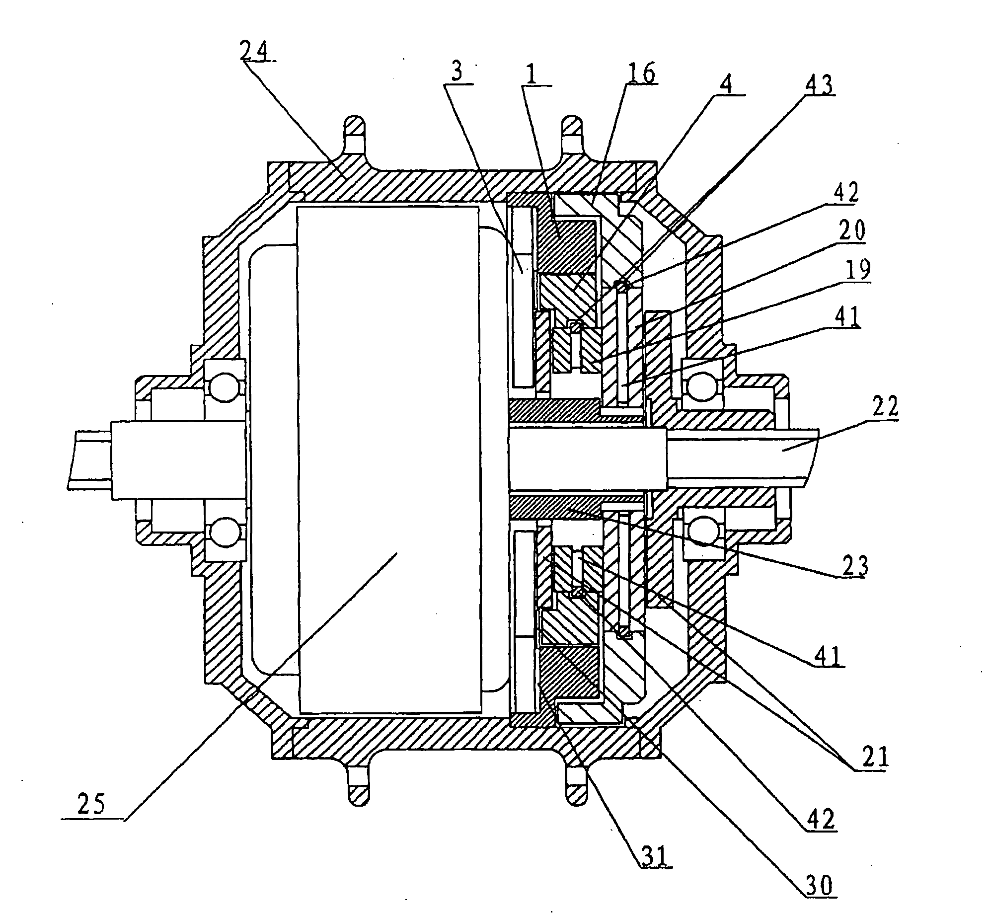
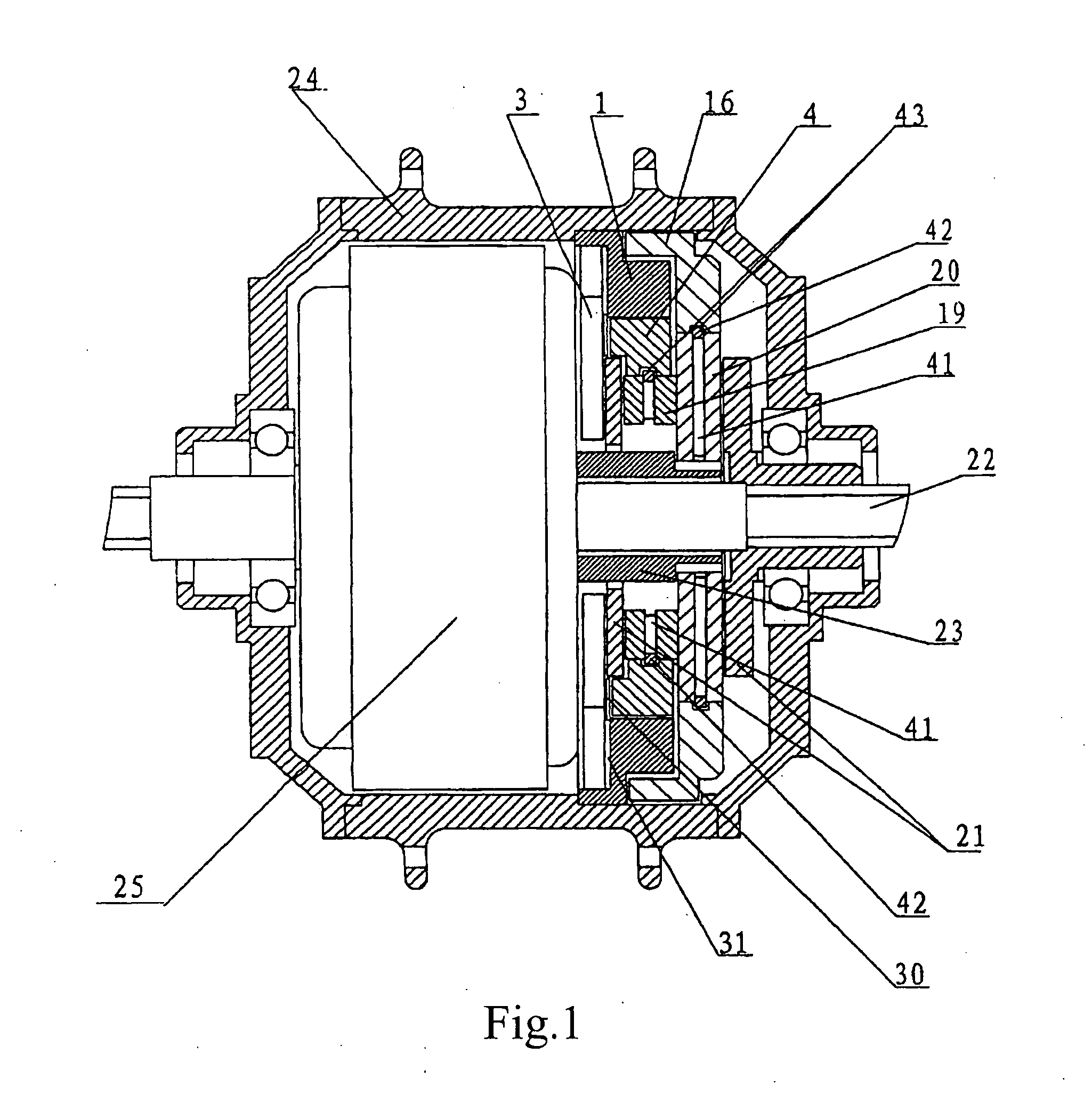
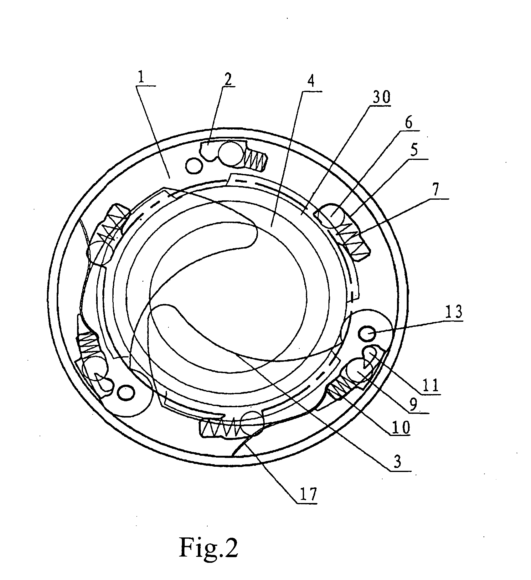
[0021]Referring to FIGS. 1 and 2, an automatic transmission for an electric vehicle hub comprises an external motor rotor 25, a sun gear 23, planet gears 19, 20, internal gears 4, 16, a planetary frame 21, a rotating disk 1, flying weights 3 (totally three, though only two are shown), an annular link 30 passing through and fixed to a motor shaft 22, where the planetary frame 21 is fixed with the motor shaft 22. Three secondary planet gears 20 (only two are shown) having external teeth are provided, circumferentially and equiangularly along the planetary frame 21, where each secondary planet gear 20 is coaxially fixed with the primary planet gear 19 having external teeth. The primary planet gear 19 has a diameter less than that of the secondary planet gear 20. The external motor rotor 25 rotates the sun gear 23 which is fixed on the motor shaft 22. The three secondary planet gears 20, the sun gear 23, and a secondary internal gear 16 are engaged with one another for rotation. The pri...


PUM


Abstract

An automatic transmission for an electric vehicle hub includes an external motor rotor fixedly connected with a motor shaft; a sun gear; at least three primary planet gears which are engaged with the sun gear; and at least three secondary planet gears coaxially fixed with the primary planet gears. The primary and the secondary planet gears are engaged with a primary and a secondary internal gears, and the secondary internal gear has a diameter greater than that of the primary internal gear. The rotating disk is arranged between the primary internal gear and the secondary internal gear, and a hub is fixed to exterior of the rotating disk. The automatic transmission further includes a clutch device, making the rotating disk and the primary internal gear contact with each other for a transmission of slower rpm, and when the rpm reaches critical, at a high-speed rotation.

Description

BACKGROUND OF THE INVENTION[0001]1. Field of the Invention[0002]The present invention relates to a transmission for vehicles, more particularly, to an automatic transmission for electric bicycle hubs.[0003]2. Description of Related Art[0004]In Chinese Patent Application No. CN2740439, filed by the same inventor and published on Nov. 16, 2005, an automatic transmission for an electric vehicle hub has been disclosed. In the prior art transmission structure, when the clutch device stays at an overdrive engagement status, particularly at a low-speed status, the overdrive engagement is not sufficiently sensitive. As such, a significant noise occurs from inside of the transmission, due to a great friction incurred between the clutch fork and the ratch, so that wearing out takes place therebetween.SUMMARY OF THE INVENTION[0005]An object of the present invention is to provide an automatic transmission for electric vehicle hubs, having merits on sensitive overdrive engagement, simple structu...

Claims


Application Information

Patent Timeline
Patent Type & Authority Applications(United States)
IPC IPC(8): B62M25/00B62M6/65
CPCB62M6/65
Inventor LIN, XIANG-YI
Owner FAIRLY BIKE MFG
Why Eureka
Try Eureka