
Aerial delivery system

a technology of delivery system and airframe, which is applied in the direction of aircraft, transportation and packaging, emergency equipment, etc., can solve the problems of reducing the risk of enemy anti-aircraft fire, and affecting the safety of personnel

Inactive Publication Date: 2009-01-29
STRONG EDWARD
View PDF26 Cites 47 Cited by
  • Summary
  • Abstract
  • Description
  • Claims
  • Application Information

AI Technical Summary

Problems solved by technology

The supplies, once deployed, are subject to drift due to wind and may also encounter enemy fire causing failure of delivery.
Accuracy and success of delivery can sometimes be increased by taking into consideration the effects of airplane and wind velocity vectors, but changes in wind direction often cause deliveries to drift off into unintended areas and enemy hands.
To further increase the accuracy of aerial deliveries, airplanes may fly at lower altitudes so that the potential for drift is reduced; however, this may increase the risk of exposure to enemy anti-aircraft fire.

Method used


Image

  • Aerial delivery system
  • Aerial delivery system
  • Aerial delivery system

Examples


Embodiment Construction

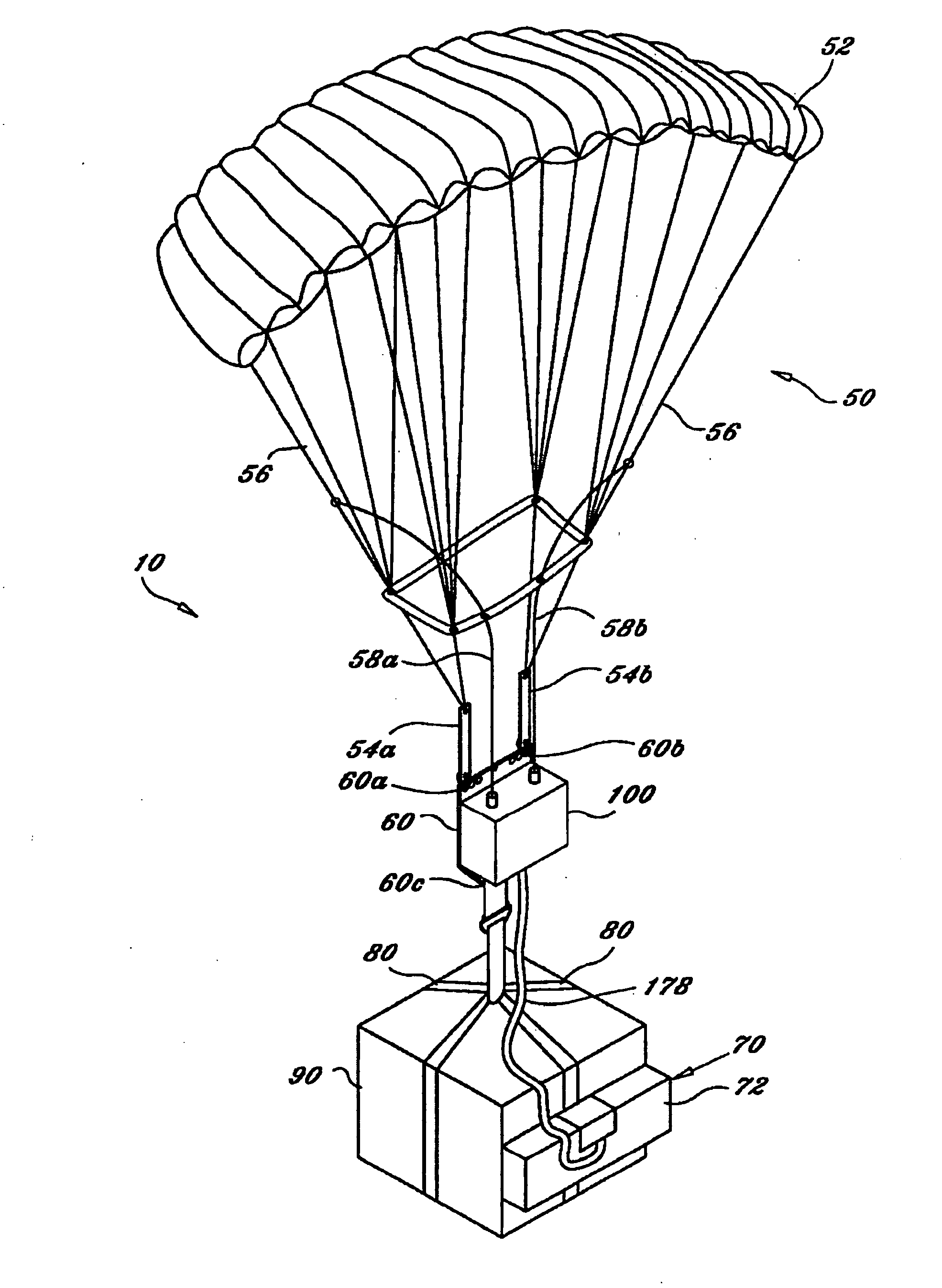
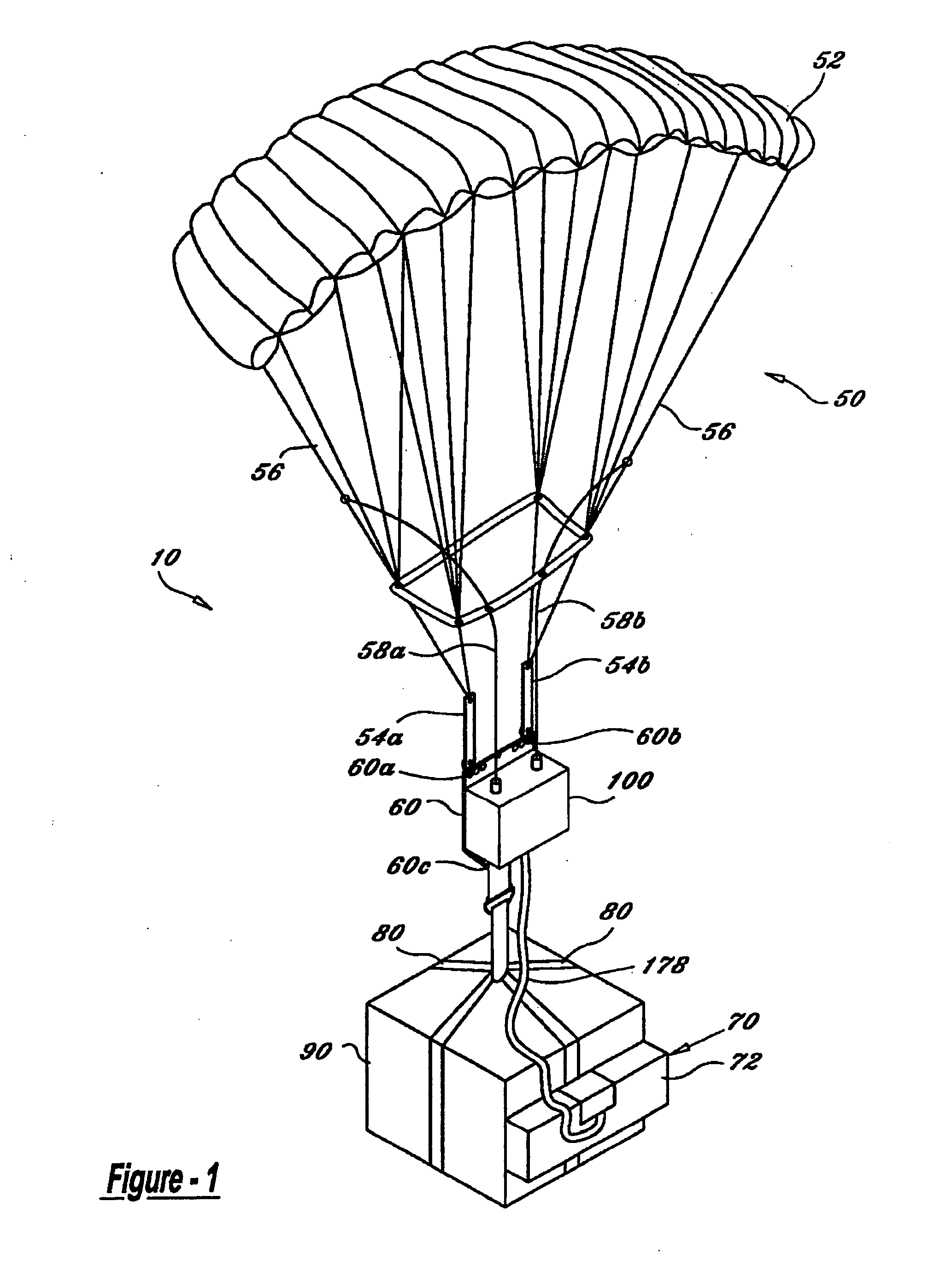
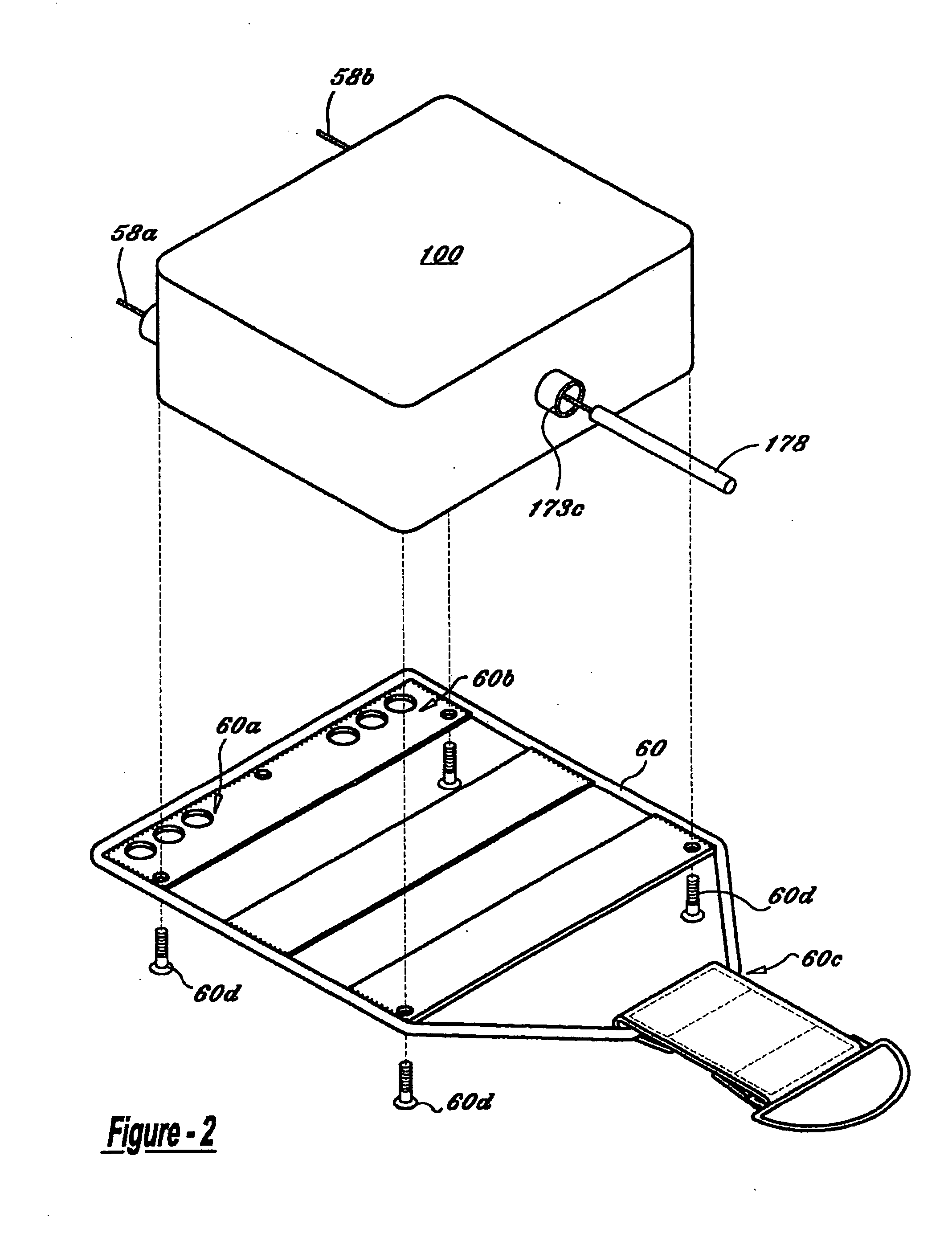
[0038]Referring now to FIG. 1, there is seen aerial delivery system 10 with an exemplary ram-air parachute 50 fully inflated. For example, aerial delivery system 10 may comprise a ram-air parachute 50, a control box 100, at least one recovery parachute 70, payload 90, and / or one or more means for retaining / securing the payload 90, such as payload support straps 80. A means for controlling descent orientation, such as suspension plate 60, may be attached between ram-air parachute 50 and the payload 90. As shown, the suspension plate 60 may be attached to, or part of, a control box 100. However, it may be preferred for the control box 100 to serve as the means for controlling descent without reliance upon the suspension plate 60, by means such as, for example, those shown below in FIGS. 9 and 10.

[0039]Payload 90 can be safely secured to the bottom of suspension plate 60 at payload suspension point 60c by one or more payload support straps 80. Payload 90 can be attached at a single poi...


PUM


Abstract

An aerial delivery system including a ram-air parachute, one or more recovery parachutes, a mantle removably attached to a cargo, and a controller operably connected to the mantle, the ram-air parachute, and the one or more recovery parachutes. The controller may be configured to receive location information associated with a target, receive information related to an ambient condition, determine a recovery parachute opening point based on the target information and the ambient condition, and cause a navigation of the aerial delivery system to the determined recovery parachute opening point.

Description

[0001]This application is a continuation-in-part of U.S. patent application Ser. No. 11 / 493,944, filed May 25, 2006, which is a continuation of application of U.S. patent application Ser. No. 10 / 709,186, filed Apr. 20, 2004, now U.S. Pat. No. 7,059,570, issued Jun. 13, 2006, and entitled “Aerial Delivery Device.” The subject matter of U.S. patent application Ser. No. 11 / 493,944 and U.S. Pat. No. 7,059,570 is hereby incorporated by reference.TECHNICAL FIELD[0002]The present disclosure relates generally to aerial delivery systems and more specifically to guided aerial delivery systems, which may be used to deliver payload and supplies to an intended target.BACKGROUND INFORMATION[0003]Aerial delivery systems are often used in the military to deliver vital equipment and supplies from planes flying at varying altitudes to specific ground targets. Typically a plane will fly overhead of the intended ground target, and the supplies or equipment will be dropped from the plane at a calculated...

Claims


Application Information

Patent Timeline
Patent Type & Authority Applications(United States)
IPC IPC(8): B64D17/00
CPCB64C39/024B64C2201/105B64C2201/107B64C2201/128B64C2201/141B64D17/74B64D17/08B64D17/44B64D17/54B64D17/64B64D1/08B64U10/50B64U2201/10B64U2101/69B64U2201/20
Inventor STRONG, EDWARD
Owner STRONG EDWARD
Learn More