Dynamic solar tracking system

a solar tracking and dynamic technology, applied in the direction of photovoltaics, moving/orienting solar heat collectors, heat collector mounting/support, etc., can solve the problems of affecting the cost, the solar energy is developing a considerably slower rhythm, and the lack of raw materials, so as to achieve the effect of optimal energy installation efficiency

Inactive Publication Date: 2009-01-29
SUNERGY PIVOT
View PDF7 Cites 13 Cited by
  • Summary
  • Abstract
  • Description
  • Claims
  • Application Information

AI Technical Summary

Benefits of technology

[0023]As will be understood, the system proposed by the invention provides an effective solar tracking means for an optimal efficiency of the energy install

Problems solved by technology

Solar energy, however, is developing a considerably at a considerably slower rhythm than that necessary for reaching final objectives.
The development of raw material for the construction pf solar cells, because one of the obstacles faced by the sector is the lack of raw material (solar grade silicon), and
If the surface of the panel is chosen to be increased

Method used


Image

  • Dynamic solar tracking system
  • Dynamic solar tracking system
  • Dynamic solar tracking system

Examples


Embodiment Construction

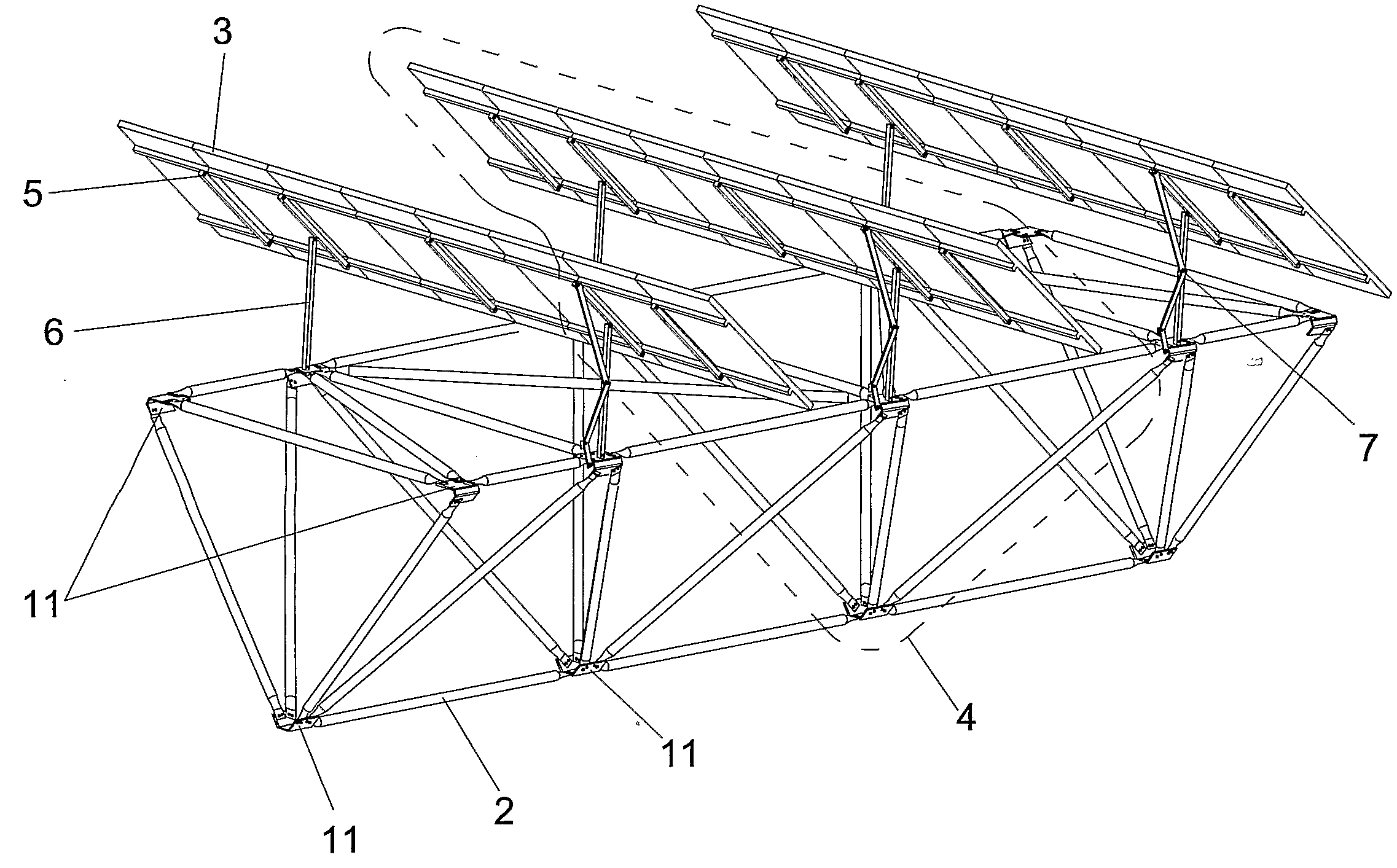
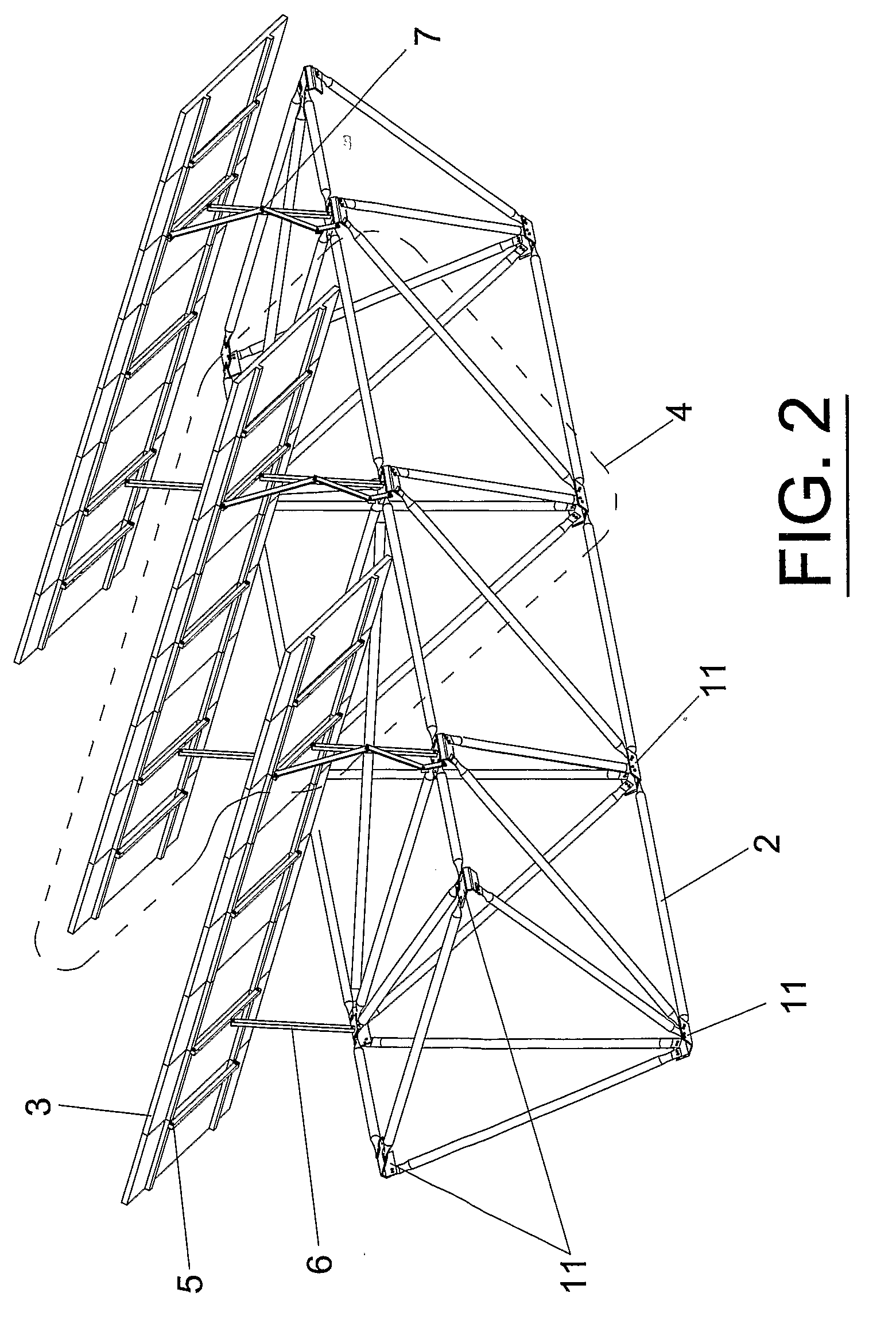
[0028]As has been indicated in the foregoing, the detailed description of the preferred embodiment of the invention will be carried out below with the aid of the attached drawings, in which the same reference numbers are used to designate identical or similar parts. Thus, considering first the illustration of FIG. 1, a schematic elevational view of a tracker designed and constructed according to the invention can be seen, which tracker is formed by pivoting beams 2 with one degree of freedom which are supported by two supports 1 at the end, the intermediate supports 1 being useful for supporting two beams, thus facilitating the successive and repetitive installation of the beams in respectively aligned positions. As can be seen in more detail in the illustration of FIG. 2, each beam 2 is in turn formed by multiple modules 4 placed following the longitudinal dimension thereof; each of such modules adopts a tetrahedral configuration which is coupled to the immediately previous and nex...


PUM


Abstract

The invention relates to a dynamic solar tracking system for making optimal use of solar energy by means of panels of photovoltaic or thermal plates, in which a modular tracker adopting the configuration of a main beam which can be aligned with others of an identical nature is developed, this assembly of main beams being able to pivot with respect to its longitudinal axis, each of these beams being formed by a variable number of modules formed by profiles which as a whole provide each beam with a configuration by way of a tetrahedron mesh, and in each of which there is assembled a secondary beam structure for supporting the panels of plates, this secondary structure being supported by two side supports with respect to which it can rotate with respect to an axis transverse to the longitudinal direction of the main beams. The assembly incorporates control means for the automatic orientation of the panels, and a weather station for providing information to the control means.

Description

OBJECT OF THE INVENTION[0001]The present invention relates to a dynamic solar tracking system providing essential novelty features and considerable advantages with respect to the known means used for the same purposes in the current state of the art.[0002]More specifically, the invention proposes the development of a solar tracker implemented around a modular beam structure according to its longitudinal direction, which structure can rotate about its longitudinal axis and is formed of profiles joined in a tetrahedron mesh and in which other structures or panels containing solar plates are supported, which structures or panels also pivot with respect to an axis transverse to the length of the beam. The assembly includes a control system prepared to act on the beam and the structures supporting the panels, such that said solar plates are automatically maintained in an optimal solar receiving position for a maximum energy generation.[0003]The field of application of the invention is ob...

Claims


Application Information

Patent Timeline
IPC IPC(8): H01L35/02
CPCF24J2/5233F24J2/5424H02S20/00Y02E10/50Y02E10/47H02S20/32H02S20/10F24S30/455F24S25/13F24S25/00
Inventor PARRA CEBRIAN, VINCENTEROJAS GOMEZ, MANUEL
Owner SUNERGY PIVOT
Why Eureka
Try Eureka