
Method And Control System For Reducing The Fatigue Loads In The Components Of A Wind Turbine Subjected to Asymmetrical Loading Of The Rotor Plane

a technology of asymmetric loading and control system, which is applied in the direction of material dimension control, non-positive displacement fluid engine, liquid fuel engine components, etc., can solve the problems of wind turbulence, more complex wind shear distribution, and non-uniform load to each rotor blade, so as to facilitate the overall data processing and facilitate the link in time

Inactive Publication Date: 2009-01-22
VESTAS WIND SYST AS
View PDF33 Cites 36 Cited by
  • Summary
  • Abstract
  • Description
  • Claims
  • Application Information

AI Technical Summary

Benefits of technology

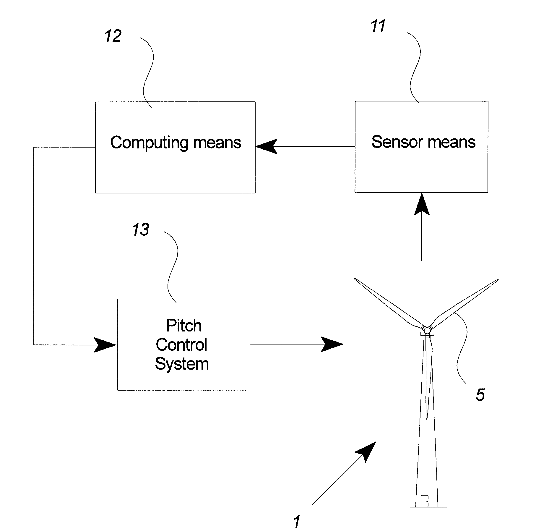
[0015]Hereby it is possible to reduce the fluctuating loads on the wind turbine components which facilitate less mechanical wear and tear on the most load-exposed parts of the wind turbine which in turn results in less required service, fewer break-downs and a prolonged life-span for the wind turbine. Alternatively it is hereby possible to increase the power capture of the wind turbine and maintain a low load on the rotor or combinations hereof.
[0017]In another aspect of the invention, the frequencies of said plurality of periodic functions is limited series of different integer multiples of the rotor frequency e.g. up to four times the rotor frequency such as any of first, second, third and fourth multiply of the rotor frequency or combinations of at least two of said multiplies. By using limited series of periodic functions it is possible to quickly establish a pitch correction in close proximity of the desired, without requiring significant computational power.
[0018]In another aspect of the invention, at least an amplitude component and a phase component are determined for each of said derived periodic functions. Determining said amplitude and phase components facilitates the overall data processing in the computing means and facilitates the link in time and azimuth location between the asymmetrical rotor load and the corrective pitch action.
[0019]In another aspect of the invention, said plurality of periodic functions includes at least one function with a frequency equal to the rotor frequency. By including periodic functions with a frequency equal to rotor frequency, it is possible to approximate a pitch correction close to the desired, simplified in a free or near free wind inflow situation.
[0020]In another aspect of the invention, said plurality of periodic functions includes at least one function with a frequency equal to four times the rotor frequency. By including periodic functions with a frequency equal to four times the rotor frequency, it is possible to approximate a pitch correction close to the desired, simplified in a partly or full wake situation.
[0021]In another aspect of the invention, said plurality of periodic functions are derived by means of a Discrete Fourier Transform applied to the load distribution function. By using Discrete Fourier Transformation to derive said plurality of periodic functions, it possible to use well known, fast and liable programming techniques to implement the program code on the computing means.

Problems solved by technology

Especially for large rotor diameters, the distribution of the wind inflow profile can be non-uniform over the area of the rotor, resulting in a non-uniform load to each rotor blade as a function of one full rotation, as well as asymmetrical out of plane loadings for the drive train of the wind turbine.
This results in a more complex wind shear distribution than compared to a free wind inflow situation.
The said complex wind distribution profile can result in wind turbulence and in turn fluctuating fatigue loads on the wind turbine components.
So in order to avoid too much wind turbulence around the turbines, downstream wind turbines are spaced relative far apart resulting in very area consuming wind parks.

Method used


Image

  • Method And Control System For Reducing The Fatigue Loads In The Components Of A Wind Turbine Subjected to Asymmetrical Loading Of The Rotor Plane
  • Method And Control System For Reducing The Fatigue Loads In The Components Of A Wind Turbine Subjected to Asymmetrical Loading Of The Rotor Plane
  • Method And Control System For Reducing The Fatigue Loads In The Components Of A Wind Turbine Subjected to Asymmetrical Loading Of The Rotor Plane

Examples


Embodiment Construction

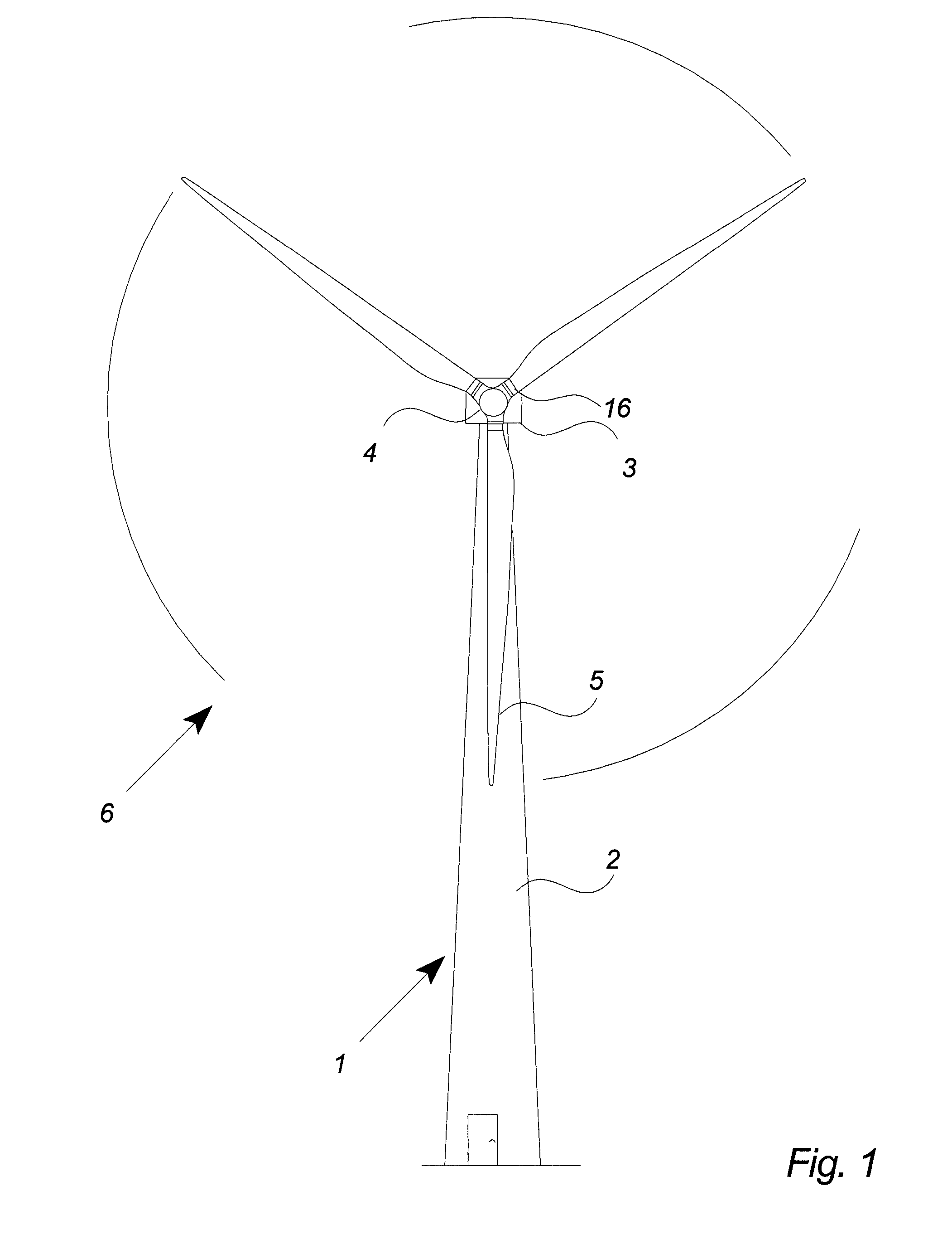
[0051]FIG. 1 illustrates a modern wind turbine 1 with a tower 2 and a wind turbine nacelle 3 positioned on top of the tower.

[0052]The wind turbine rotor, comprising at least one blade such as three wind turbine blades 5 as illustrated, is connected to the hub 4 through pitch mechanisms 16. Each pitch mechanism includes a blade bearing and pitch actuating means which allows the blade to pitch in relation to the wind. The pitch process is controlled by a pitch controller as will be further explained below.

[0053]The blades 5 of the wind turbine rotor are connected to the nacelle through the low speed shaft 4 which extends out of the nacelle front.

[0054]As illustrated in the figure, wind over a certain level will activate the rotor and allow it to rotate in a perpendicular direction to the wind. The rotation movement is converted to electric power which usually is supplied to the transmission grid as will be known by skilled persons within the area.

[0055]FIG. 2 illustrates how the Azimu...


PUM


Abstract

The invention relates to a method for reducing fatigue loads in the components of a wind turbine subjected to asymmetrical loading of its rotor, comprising the steps of: repeatedly collecting and storing load data of the rotor, determining a load distribution function for the rotor from said stored data, deriving a plurality of periodic functions from said load distribution function, determining actions for the wind turbine control means for reducing the fatigue load of the wind turbine components from said derived plurality of periodic functions, and implementing of said determined actions on the wind turbine control means. The invention also relates to a control system as well as a wind turbine and wind park.

Description

CROSS-REFERENCE TO RELATED APPLICATIONS[0001]The present application is a continuation of pending International patent application PCT / DK2006 / 000153, filed Mar. 16, 2006, which designates the United States, the content of which is incorporated herein by reference.FIELD OF THE INVENTION[0002]The present invention relates to a method for reducing fatigue loads in the components of a wind turbine, a control system for reducing the fatigue loads in the components of the wind turbine subjected to asymmetrical loading of the rotor plane, a wind turbine and a wind park.BACKGROUND OF THE INVENTION[0003]Wind turbine controllers have been deployed in wind turbines for years with the purpose of controlling the overall power output.[0004]The power output from a modern wind turbine can be controlled by means of a control system for regulating the pitch angle of the rotor blades. The rotor rotation speed and power output of the wind turbine can hereby be initially controlled e.g. before a transfe...

Claims


Application Information

Patent Timeline
Patent Type & Authority Applications(United States)
IPC IPC(8): F03D7/04F03D7/00
CPCF03D7/0292F03D7/042Y02E10/723F05B2270/332F05B2270/1095Y02E10/72F03D7/0224F03D7/0232
Inventor PEDERSEN, BO JUUL
Owner VESTAS WIND SYST AS
Learn More