
System and method for vapor control in cryogenic freezers

a technology of cryogenic freezer and vapor control, which is applied in the field of cryogenic refrigeration and freezing systems, can solve the problems of increased costs of operating the cryogenic refrigeration system, inefficient cryogen usage, and water vapor deposition inside the freezer

Inactive Publication Date: 2009-01-22
PRAXAIR TECH INC
View PDF8 Cites 14 Cited by
  • Summary
  • Abstract
  • Description
  • Claims
  • Application Information

AI Technical Summary

Benefits of technology

The present invention is a cryogenic freezer system that includes a freezer compartment, a cryogen supply subsystem, an exhaust subsystem, a control subsystem, and temperature sensors. The control subsystem is responsible for controlling the cryogen and the transition fan based on the temperature differences between the process room, the freezer compartment, and the exhaust. The technical effect of this invention is to efficiently control the cryogenic freezer system to maintain the desired temperature for food preservation.

Problems solved by technology

Running the exhaust fans and transition fans at the same speed may result in the exhaust system forcing cryogen vapors out of the refrigeration equipment before some of the refrigeration energy can be extracted.
In addition, running the exhaust fans and transition fans at the same speed may also result in pulling excess fresh air into the freezer that needs to be refrigerated which, in turn may cause deposition of water vapor from the excess room air inside the freezer.
Both of these problems, namely inefficient cryogen usage as well as excess room air tend to increase costs of operating the cryogen refrigeration system.
For example, if the food-process room temperature were to vary, such process room temperature change would likely affect the exhaust temperature causing erroneous adjustments in fan speed leading to inefficiencies in freezer operation.

Method used


Image

  • System and method for vapor control in cryogenic freezers
  • System and method for vapor control in cryogenic freezers

Examples


Embodiment Construction

[0010]The following description sets forth the best mode presently contemplated for practicing the present cryogenic freezer system with vapor control. It is not to be taken in a limiting sense, but rather should be read in conjunction with the appended claims.

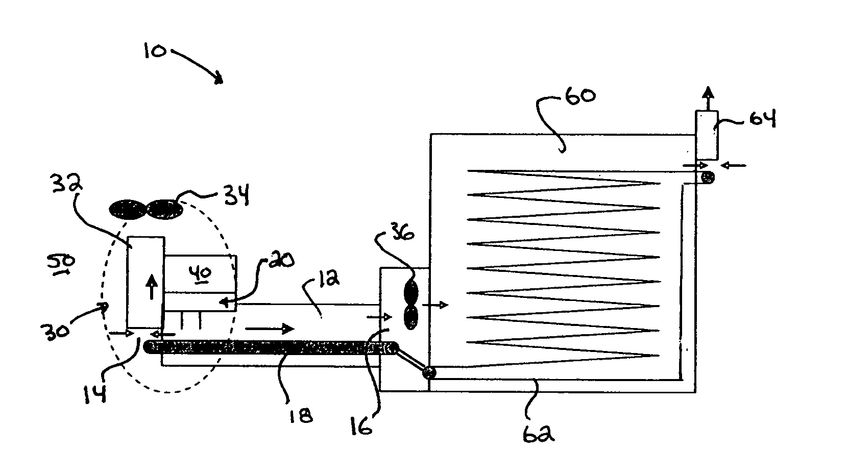
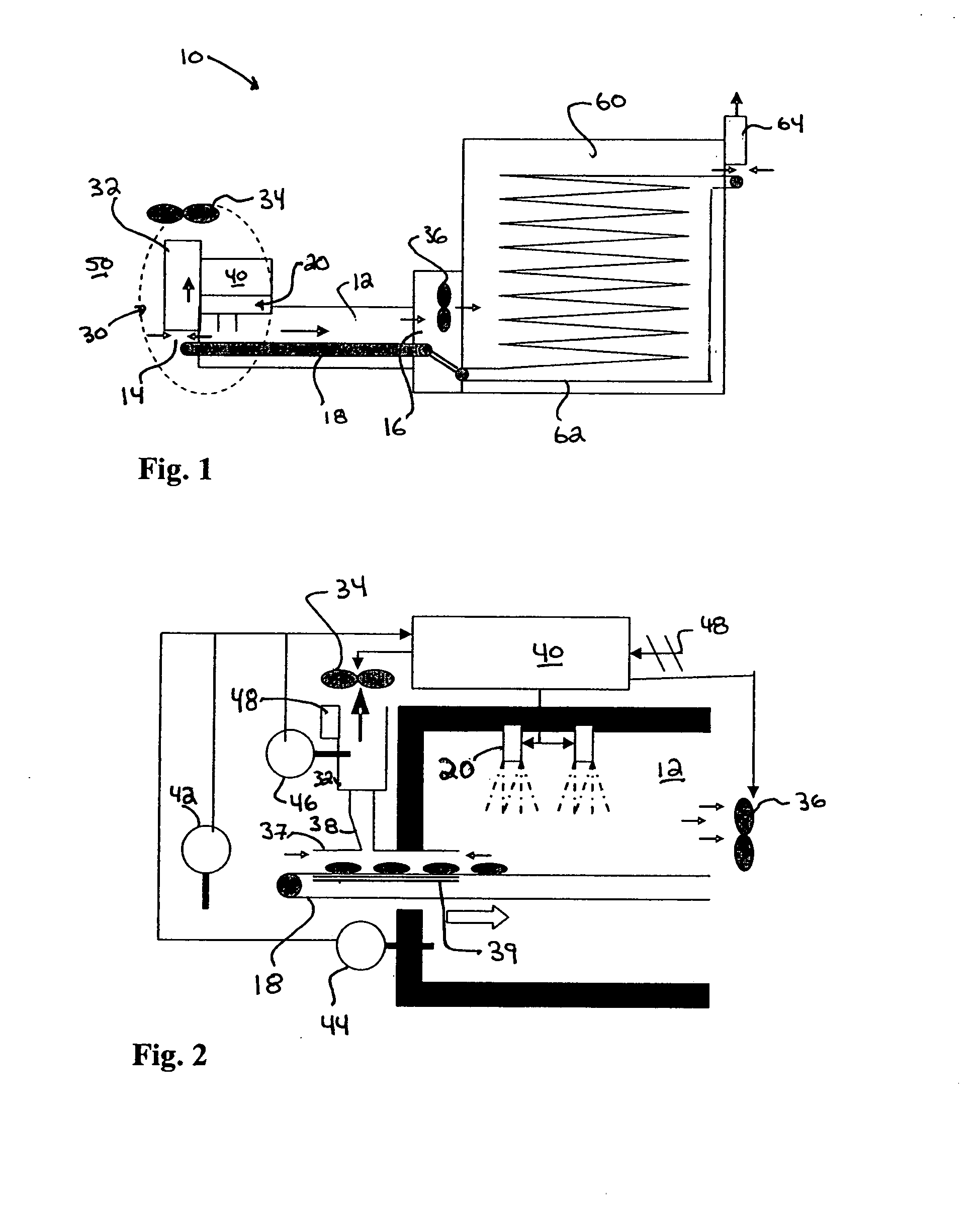
[0011]With reference to FIG. 1 and FIG. 2, there is shown an embodiment of the present cryogenic freezer system 10 with vapor control. As seen therein, the cryogenic freezer system 10 includes a first freezer compartment 12 having an entrance 14, an exit 16, and a conveyor 18 disposed therein for treating a food product. The freezer system 10 further includes a cryogen injection or supply subsystem 20 adapted to introduce a cryogen into the first freezer compartment 12 to treat the food product as well as an exhaust subsystem 30 and a vapor control subsystem 40. In the illustrated embodiment, the exhaust subsystem 30 preferably includes an exhaust duct 32 disposed proximate the entrance 14 of the first freezer compartment 12 i...


PUM


Abstract

A cryogenic freezer with cryogenic vapor control is disclosed. The cryogenic freezer is characterized in that the vapor control system is adapted to control the speed of the transition fan which moves some of the cryogen from a first cryogenic freezer to a second freezer in response to differences between the temperature of the process room, operating temperature of the cryogenic freezer; and a temperature of the exhaust. By adjusting the transition fan speed in response to such temperature differences the vapor control system operates to limit the flow of air from the process room into the freezer and also limits cryogen vapor flow from the freezer to the process room.

Description

FIELD OF THE INVENTION[0001]The present invention relates to cryogenic refrigeration and freezing systems, and more particularly to a system and method for the control of freezer vapors within the cryogenic refrigeration and freezing systems.BACKGROUND OF THE INVENTION[0002]In many conventional cryogenic refrigeration or freezing systems, the system typically run the exhaust fans and transition fans at the same speed and usually at a speed that can handle peak cryogen usage. Running the exhaust fans and transition fans at the same speed may result in the exhaust system forcing cryogen vapors out of the refrigeration equipment before some of the refrigeration energy can be extracted. In addition, running the exhaust fans and transition fans at the same speed may also result in pulling excess fresh air into the freezer that needs to be refrigerated which, in turn may cause deposition of water vapor from the excess room air inside the freezer. Both of these problems, namely inefficient...

Claims


Application Information

Patent Timeline
Patent Type & Authority Applications(United States)
IPC IPC(8): F25D3/11
CPCF25D3/11F25D13/06F25D2700/123F25D29/001F25D16/00
Inventor GIRARD, JOHN M.SAMESHIMA, GLENN T.
Owner PRAXAIR TECH INC
Learn More