
Image transmitting apparatus, image transmitting method, receiving apparatus, and image transmitting system

a technology of image transmission and receiving apparatus, applied in the direction of selective content distribution, instruments, computing, etc., can solve the problems of waste of resources, large consumption of cpu power, and large power consumption when performed on a hardware basis, and achieve the effect of convenient display and convenient display

Inactive Publication Date: 2009-01-15
SONY CORP
View PDF22 Cites 36 Cited by
  • Summary
  • Abstract
  • Description
  • Claims
  • Application Information

AI Technical Summary

Benefits of technology

[0010]It is therefore desirable to allow an image of a selected area to be easily displayed at a receiving end.
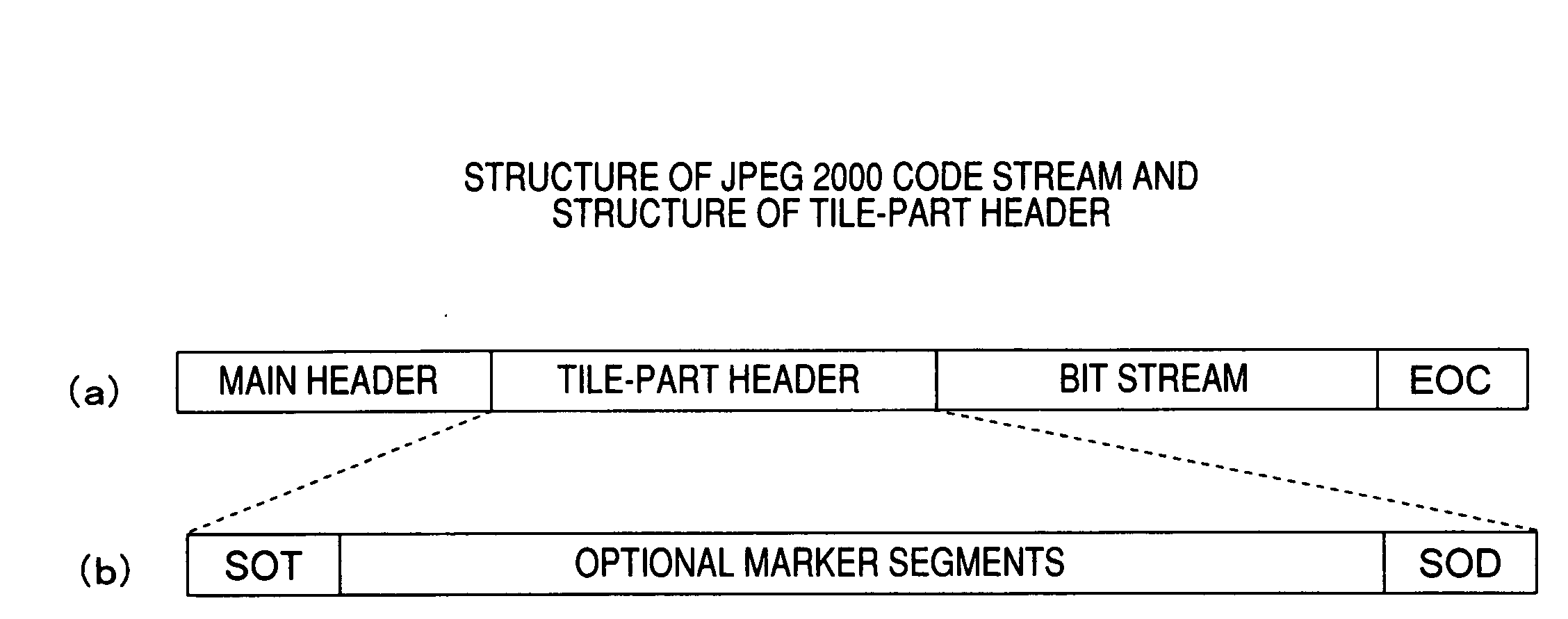
[0014]As thus, described, new image frame information that is encoded data of selected areas added with a header including configuration information of each of the selected areas is transmitted to a receiving end. Therefore, an image of the selected areas can be easily displayed at the receiving end based on the configuration information included in the header.
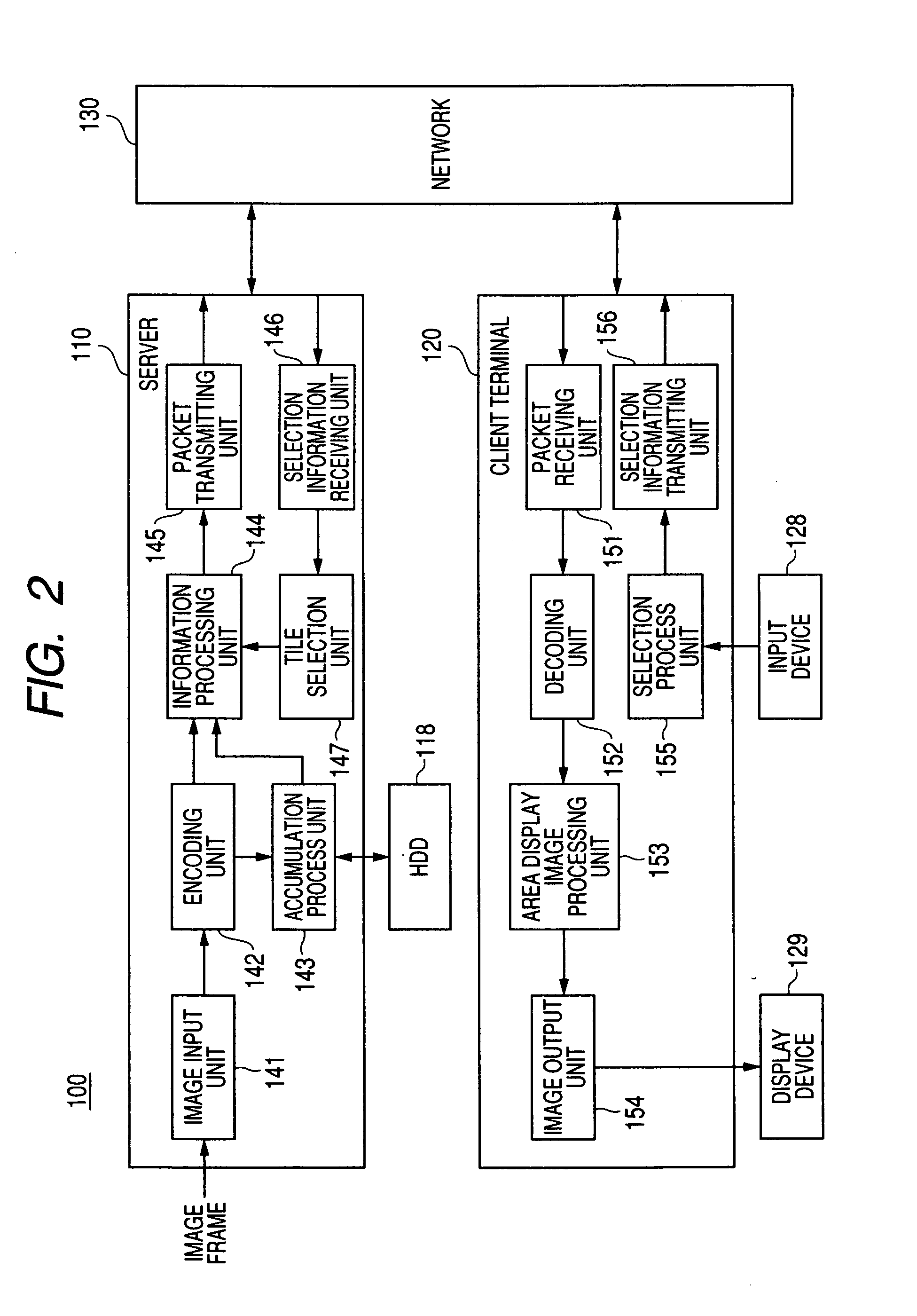
[0015]According to the embodiment of the invention, an image is transmitted based on image frame information including encoded data of a plurality of areas obtained by dividing an image frame and a header including configuration information of each area. Encoded data of selected areas is extracted, and a header including configuration information of each of the selected areas is created to generate new image frame information. The image frame information is transmitted to a receiving end, and an image of the selected areas can be easily displayed at the receiving end.

Problems solved by technology

The process results in significant consumption of a CPU when performed on a software basis and consumes great power when performed on a hardware basis.
Either of the methods has a problem in that resources are wastefully consumed in the excess of the amount of resources required for a client terminal to process a desired area.

Method used


Image

  • Image transmitting apparatus, image transmitting method, receiving apparatus, and image transmitting system
  • Image transmitting apparatus, image transmitting method, receiving apparatus, and image transmitting system
  • Image transmitting apparatus, image transmitting method, receiving apparatus, and image transmitting system

Examples


Embodiment Construction

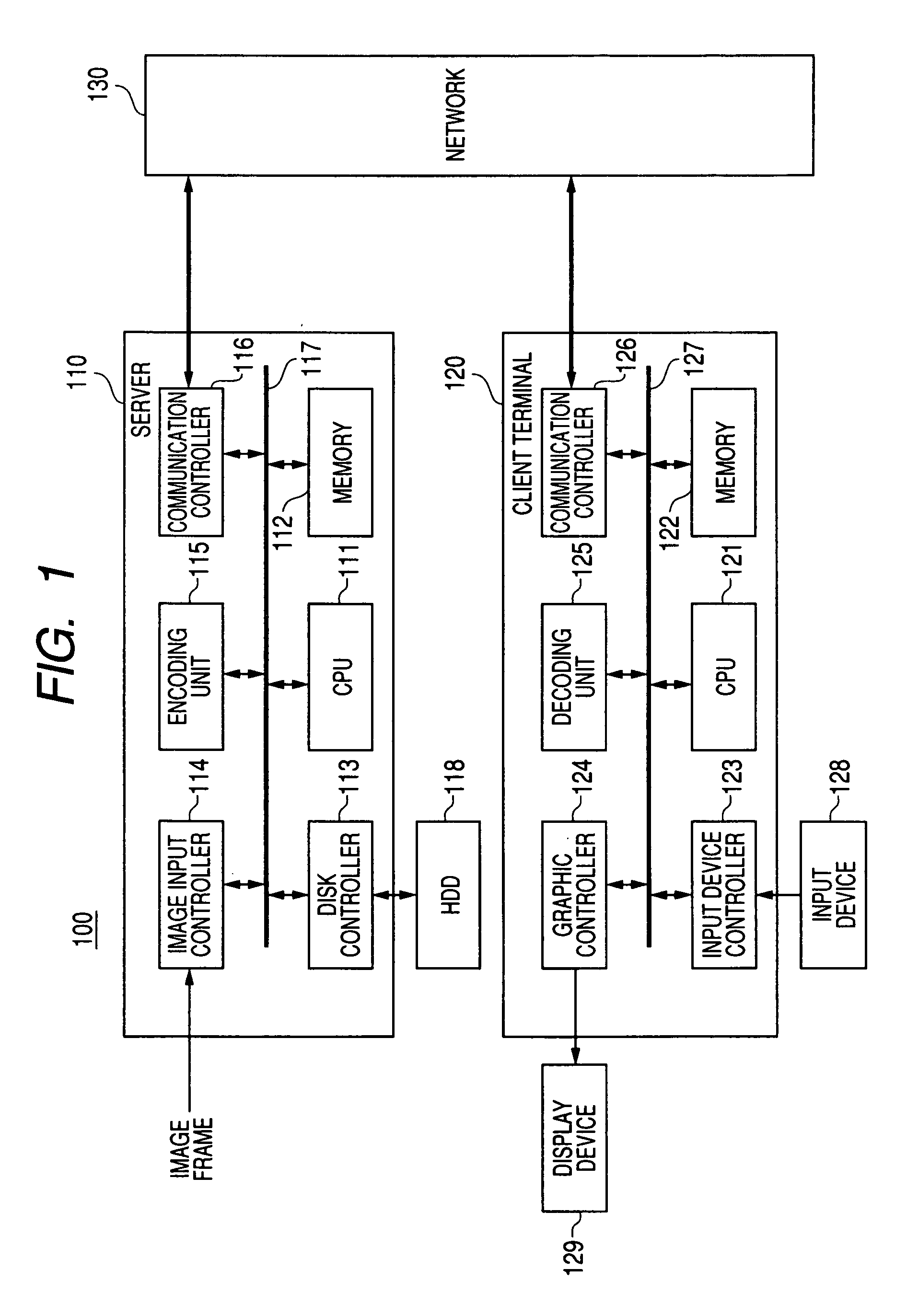
[0033]An embodiment of the invention will now be described with reference to the drawings. FIG. 1 shows an example of a configuration of an image distribution system 100 that is an embodiment of the invention.

[0034]The image distribution system 100 includes a server 110 and a client terminal 120. The client terminal 120 is connected to the server 110 through a network 130. The server 110 constitutes an image transmitting apparatus, and the client terminal 120 constitutes a receiving apparatus.

[0035]The server 110 includes a CPU (Central Processing Unit) 111, a memory 112, a disk controller 113, an image input controller 114, an encoding unit 115, and a communication controller 116. Those elements are connected to a bus 117.

[0036]The CPU 111 controls operations of the server 110 as a whole. The memory 112 includes a ROM (Read Only Memory) and a RAM (Random Access Memory). Control programs for controlling operations of the CPU 111 are stored in the ROM. The RAM serves as a working are...


PUM


Abstract

An image transmitting apparatus transmits an image based on image frame information including encoded data of a plurality of areas obtained by dividing an image frame and a header including configuration information of each area. The apparatus includes an area selecting unit selecting one area or a plurality of areas from among the plurality of areas of one image frame or a plurality different image frames, an information processing unit extracting encoded data of the area selected by the area selecting unit from encoded data of the plurality of areas included in the image frame information of the one image frame or the plurality of different image frames and creating a header including configuration information of each area selected by the area selecting unit to generate new image frame information, and an image transmitting unit transmitting the image frame information generated by the information processing unit to a receiving end.

Description

CROSS REFERENCES TO RELATED APPLICATIONS[0001]The present invention contains subject matter related to Japanese patent Application JP 2007-183988 filed in the Japanese Patent Office on Jul. 13, 2007, the entire contents of which being incorporated herein by reference.BACKGROUND OF THE INVENTION[0002]1. Field of the Invention[0003]The present invention relates to an image transmitting apparatus, an image transmitting method, a receiving apparatus, and an image transmitting system. More specifically, the invention relates to an image transmitting apparatus which processes image frame information including encoded data of a plurality of areas obtained by dividing an image frame and a header including configuration information of each area. The apparatus extracts encoded data of selected areas and creates a header including configuration information of the selected areas to generate new image frame information. The apparatus transmits the new image frame information to a receiving end s...

Claims


Application Information

Patent Timeline
IPC IPC(8): G06K9/36H04N1/41H04N19/00H04N19/102H04N19/134H04N19/136H04N19/162H04N19/164H04N19/167H04N19/176H04N19/423H04N19/46H04N19/70
CPCH04N21/2662H04N21/4728H04N21/6582H04N21/845H04N19/17H04N19/46H04N19/63H04N19/162H04N19/164H04N19/70H04N7/12H04N21/236
Inventor ITAKURA, EISABURO
Owner SONY CORP
Learn More