
Desktop organizer

a desk organizer and organizer technology, applied in the field of desk organizers, can solve the problems of scratches on the body of writing instruments, need considerable force, pick up dirt and be lost, etc., and achieve the effects of convenient and convenient removal, unique compact and aesthetic appearance, and easy and convenient picking up

Inactive Publication Date: 2009-01-15
COTAPAXI CUSTOM DESIGN & MFG
View PDF16 Cites 17 Cited by
  • Summary
  • Abstract
  • Description
  • Claims
  • Application Information

AI Technical Summary

Benefits of technology

[0012]Another advantage of the present invention is that each selected writing instrument can be easily and conveniently removed form the receptacle by rotating the platform on the base.
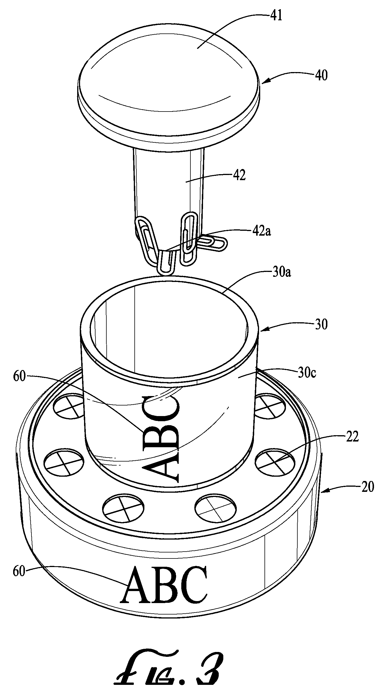
[0013]Yet another advantage of the present invention is that metal desk items such as paperclips can be easily picked up one by one when needed, using the magnet formed on an end of the plug closing the desk-item container.
[0014]Still another advantage of the present invention is that while retaining all the above-described utilities, the desktop organizer has a unique compact and aesthetic appearance that would suit the aesthetic need of a user as well in an office environment.
[0015]Lastly, the desktop organizer in the present invention has a further advantage that it can be used as an effective vehicle for advertisement by providing rather ample surfaces, the outer surface of the central column or the side walls of the platform, for placing advertising materials thereon.

Problems solved by technology

The drawbacks of this invention, however, are that the paperclips, being exposed on the tray, may pick up dirt and be lost, and further, that disengaging each writing instrument off the grip of the spring mechanism may require exertion of considerable force, and in so doing, cause scratches on the body of the writing instruments inflicted from the spring.
These inventions, however, fail to disclose a capacity of holding any writing instrument.

Method used


Image

  • Desktop organizer
  • Desktop organizer
  • Desktop organizer

Examples


Embodiment Construction

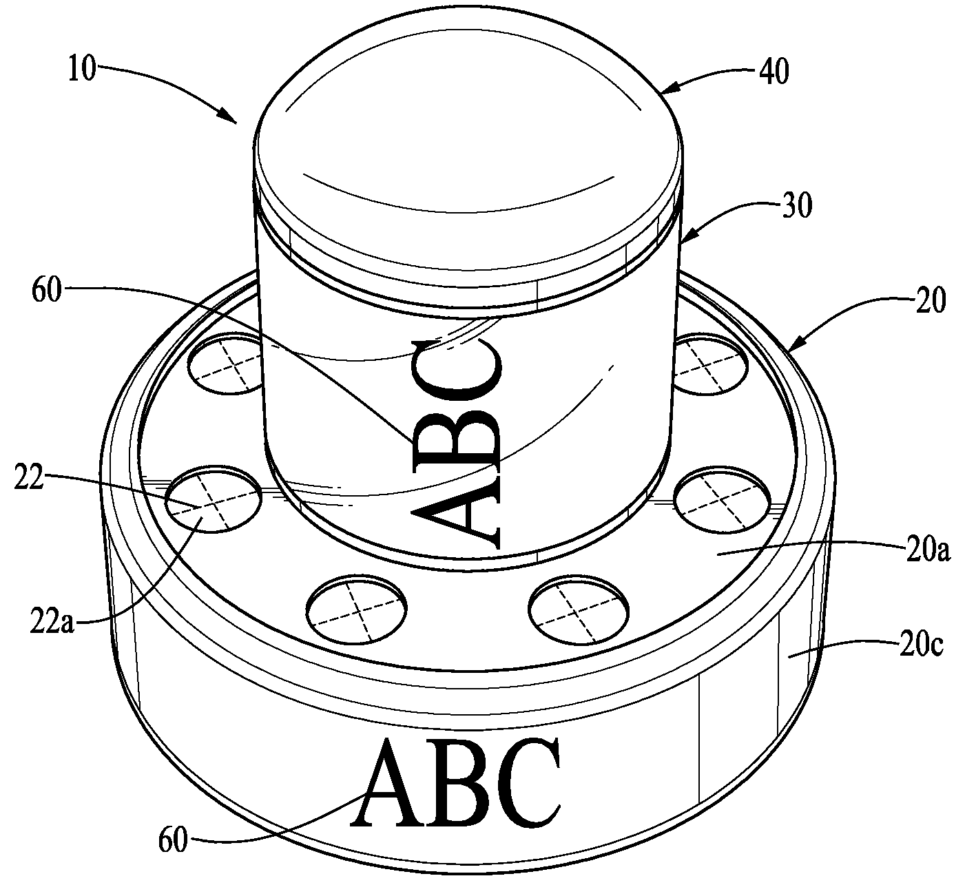
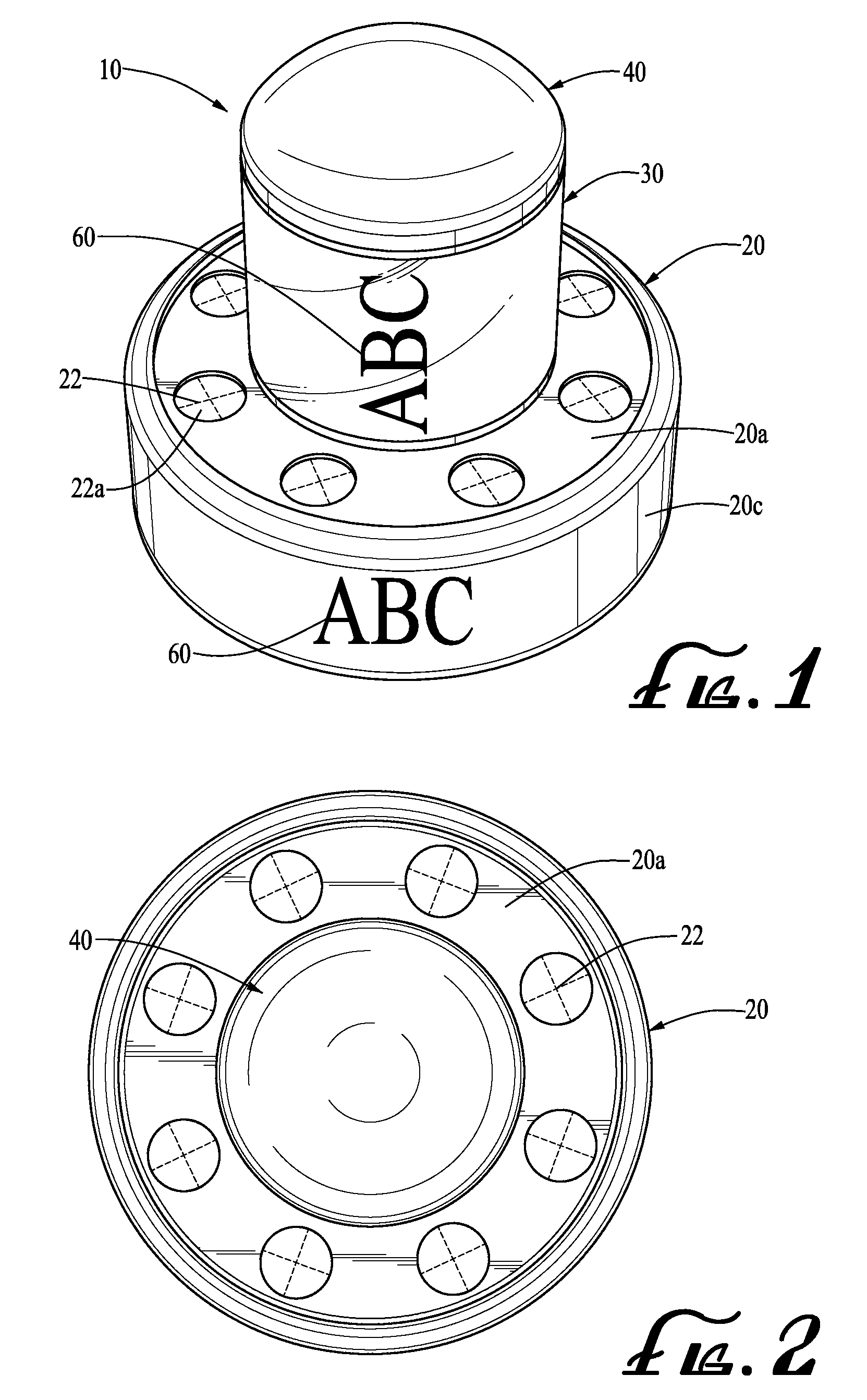
[0023]The present invention generally relates to a rotatable desktop organizer that can hold a plurality of writing instruments, each one in a separate receptacle, and store common desk items made of metal, such as paperclips, that can be conveniently removed, one by one, via a magnet.

[0024]The preferred embodiment of the present invention will now be described with reference to FIGS. (‘FIGS.’) 1-7, wherein like components are designated by like reference numerals throughout the figures. With regard to means for fastening, mounting, attaching or connecting the components of the present invention to form the assembly as a whole, unless specifically described otherwise, such means are intended to at least encompass conventional fasteners such as machine screws, machine threads, snap rings, hose clamps, rivets, nuts and bolts, toggles, pins and the like. Components may also be connected by friction fitting, snap fitting, adhesives or by welding or deformation, if appropriate. Unless sp...


PUM


Abstract

A rotatable desktop organizer for holding a plurality of writing instruments and desk items such as paperclips. The desktop organizer has a platform having a plurality of concentric receptacles along the circumference of the top platform surface for securely holding, in each of the receptacle, a single writing instrument in a substantially upright position, a hollow column with an open top protruding upward from the center of the platform for storing desk items therein, a flat base rotatably connected to the bottom of the platform to allow, by rotating the platform, easier access to a particular writing instrument selected, and a removable plug for inserting into the column which has a magnet at its distal end for thereby picking up metallic items stored in the column. The desktop organizer may further have advertising material disposed on the side surface of either the column or the platform.

Description

[0001]The present invention relates to field of an aesthetically designed, rotatable desktop organizer that can hold a plurality of wring instruments, each held in a separate receptacle, and retain metal desktop articles such as paperclips which can be conveniently picked up for use by a magnet.CROSS-REFERENCE TO RELATED APPLICATION[0002](Not Applicable)STATEMENT RE: FEDERALLY SPONSORED RESEARCH / DEVELOPMENT[0003](Not Applicable)BACKGROUND OF THE INVENTION[0004]Desktop organizers are widely used for organizing various kinds of desktop items such as writing instruments, paper clips, staples, flag or roll tapes, note pads, erasers, alarmers, clocks, or even graphic images. What users of such desktop organizers consider in making a purchase decision is not merely the variety in kinds or number of desktop items that can be held in an organizer or the utility aspect relating how conveniently and efficiently an individual desktop item can be accessed and removed from the organizer. Often t...

Claims


Application Information

Patent Timeline
IPC IPC(8): A45C11/34B43M99/00
CPCA45C11/34A45C11/36B43M99/009B43M99/006B43K23/001
Inventor CETERA, CARL
Owner COTAPAXI CUSTOM DESIGN & MFG
Learn More