Eureka AIR delivers breakthrough ideas for toughest innovation challenges, trusted by R&D personnel around the world.

Stationary Exercise Equipment

a technology for stationary exercise equipment and control systems, applied in the direction of gymnastic exercise, frictional force resistors, sport apparatus, etc., can solve the problem that known control schemes/methods do not provide force feedback that realistically

Active Publication Date: 2009-01-08
RADOW SCOTT B
View PDF99 Cites 215 Cited by
  • Summary
  • Abstract
  • Description
  • Claims
  • Application Information

AI Technical Summary

Benefits of technology

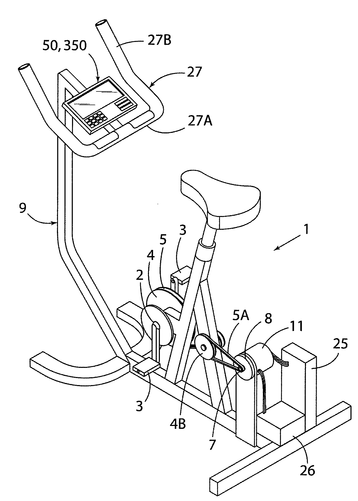
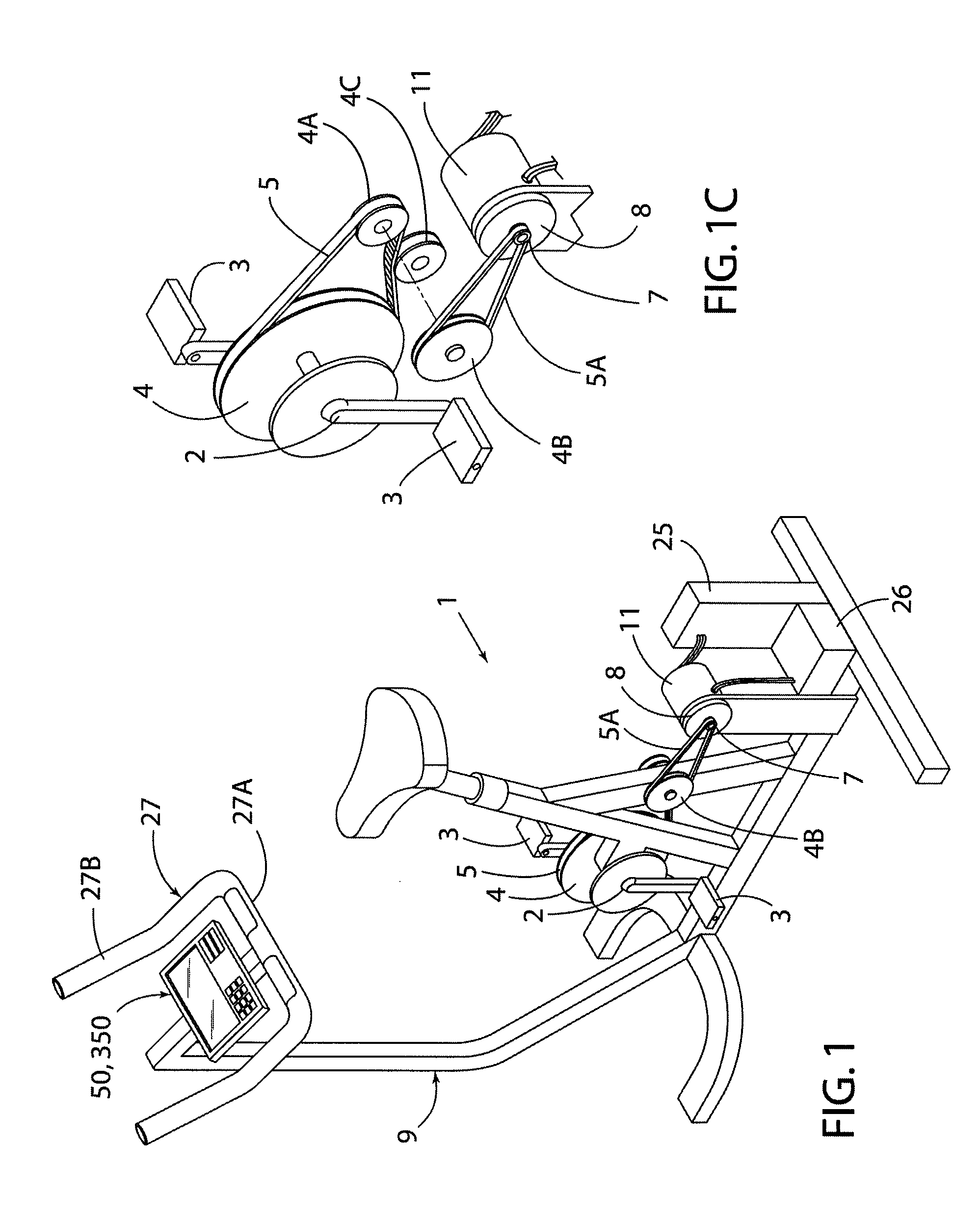
[0007]Another aspect of the present invention is a stationary bike that substantially simulates the pedaling effort of a moving bicycle. The stationary bike includes a support structure and a pedal movably mounted to the support structure. The pedal structure includes two pedals that move about an axis to define an angular velocity. Forces applied to the pedals by a user define user input forces. The stationary bike further includes a controller that is operably connected to the pedal structure to provide a variable resistance force restraining movement of the pedals in response to user input forces. The variable resistance force substantially emulates at least some of the effects of inertia that would be experienced by a rider of a moving bicycle.

Problems solved by technology

However, known control schemes / methods do not provide force feedback that realistically simulates the forces encountered when performing the actual physical activity to be simulated.

Method used


Image

  • Stationary Exercise Equipment
  • Stationary Exercise Equipment
  • Stationary Exercise Equipment

Examples


Embodiment Construction

[0052]The present application is related to U.S. Pat. No. 6,676,569, issued Jan. 13, 2004; U.S. Pat. No. 6,454,679, issued Sep. 24, 2002; and U.S. Pat. No. 7,066,865, issued Jun. 27, 2006; U.S. patent application Ser. No. 11 / 438,715, filed on May 22, 2006; and U.S. patent application Ser. No. 11 / 644,777, filed on Dec. 22, 2006, the entire contents of each are hereby incorporated by reference.

[0053]One aspect of the present invention is a control system / method for controlling an exercise device or the like. The control system / method can be utilized to simulate virtually any dynamic system. Another aspect of the present invention is an exercise device such as a stationary bike 1 (FIG. 1) that includes a dynamic system control that simulates riding a bicycle. The present invention provides a unique way to control an exercise device to more accurately simulate the dynamics of the exercise being simulated.

[0054]Various types of exercise equipment have been developed in an attempt to imit...


PUM


Abstract

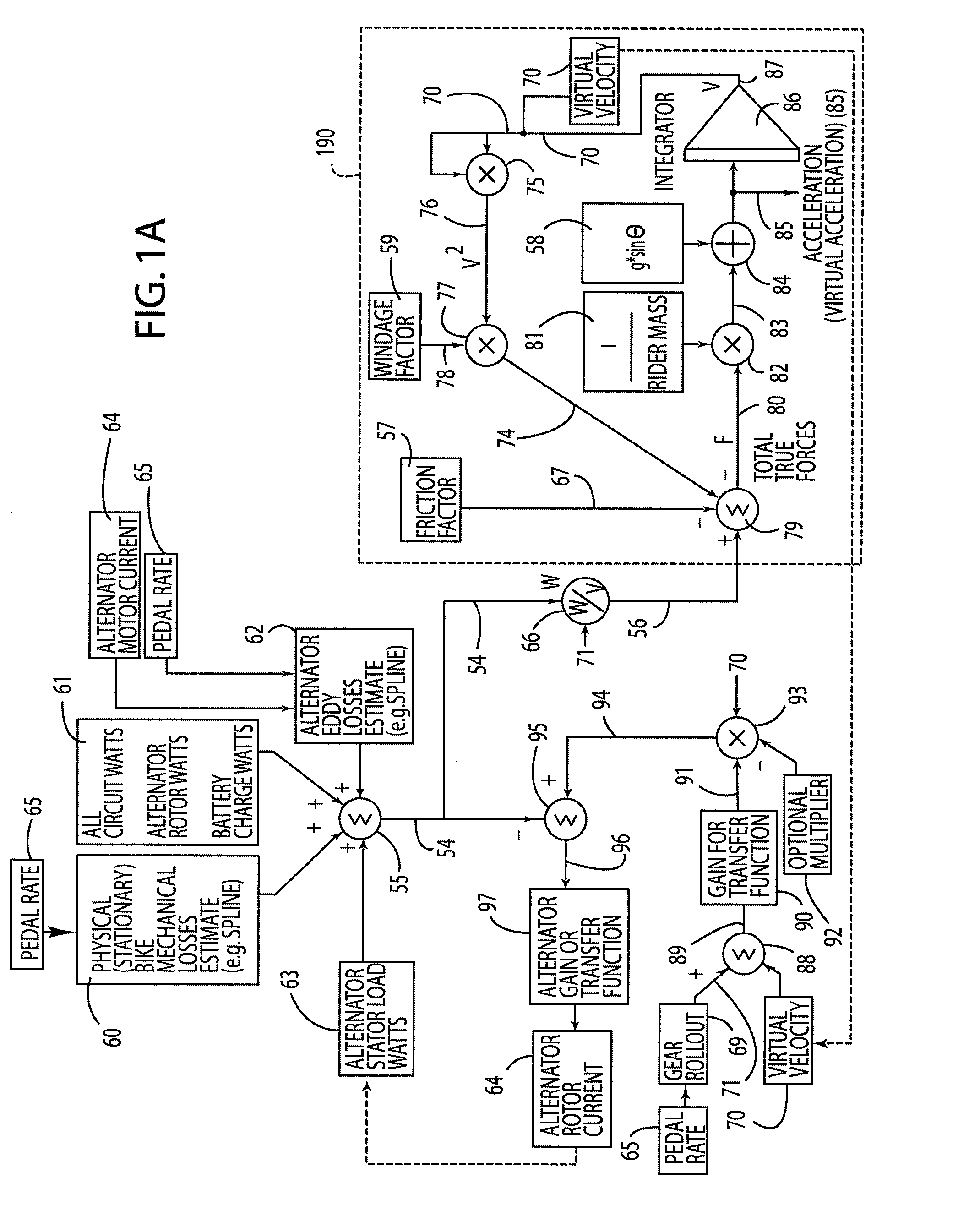
A control system and method for exercise equipment and the like provides a way to simulate a physical activity in a manner that takes into account the physics of the physical activity being simulated to provide an accurate simulation. According to one aspect of the present invention, the control system and method takes into account the physics of the corresponding physical activity to generate a virtual or predicted value of a variable such as velocity, acceleration, force, or the like. The difference between the virtual or expected physical variable and a measured variable is used as a control input to control resistance forces of the exercise equipment in a way that causes the user to experience forces that are the same or similar to the forces that would be encountered if the user were actually performing the physical activity being simulated rather than using the exercise equipment.

Description

CROSS REFERENCE TO RELATED APPLICATIONS[0001]This application claims the benefit of U.S. Provisional Application No. 60 / 946,568, filed on Jun. 27, 2007, entitled STATIONARY EXERCISE EQUIPMENT, the entire contents of which are incorporated herein by reference.BACKGROUND OF THE INVENTION[0002]Various types of exercise devices such as stationary bikes, treadmills, stair climbers, rowing machines, and the like, have been developed. Such exercise devices mimic a corresponding physical activity to some degree. For example, known stair climbing machines typically include movable foot supports that reciprocate to simulate to some degree the foot and leg motion encountered when climbing stairs. Known stationary bikes typically include a crank with pedals that rotate upon application of a force to the pedals by a user.[0003]Various ways to control the forces generated by such exercise devices have been developed. Known control schemes include constant-force arrangements and constant-power arr...

Claims


Application Information

Patent Timeline
Patent Type & Authority Applications(United States)
IPC IPC(8): A63B22/06
CPCA63B21/00181A63B24/0084A63B2024/009A63B2220/34A63B2022/0658A63B2225/107A63B2225/20A63B22/0605A63B2220/51A63B69/0057A63B71/0622A63B21/0051A63B21/0053A63B21/0058A63B21/015A63B21/225A63B22/02A63B22/04A63B24/0087B62M3/00A63B2024/0093A63B2024/0096A63B2071/0638A63B2071/0644A63B2220/17A63B2220/30A63B2220/40H02K49/046H01H9/54
Inventor RADOW, SCOTT B.BLAU, DAVID A.
Owner RADOW SCOTT B
Why Eureka
Eureka Blog
Learn More