
Spindle Motor

a spindle motor and spindle technology, applied in the direction of rotating magnets, synchronous machines with stationary armatures, mechanical energy handling, etc., can solve the problem of increasing surface vibration in the axial direction of the disk much, and achieve the effect of reducing surface vibration

Inactive Publication Date: 2009-01-01
LG INNOTEK CO LTD
View PDF8 Cites 0 Cited by
  • Summary
  • Abstract
  • Description
  • Claims
  • Application Information

AI Technical Summary

Benefits of technology

"The patent text describes a spindle motor that can reduce surface vibrations in a disk by interrupting the rotation of the shaft or the floating of the rotor. The motor includes a bearing housing, a bearing fixed inside the housing, a rotating shaft, a stator, a rotor, and a magnet. The motor can be designed to attract the rotating shaft in one direction or in a downward direction. The technical effect of this invention is to improve the performance and stability of spindle motors in disk drives."

Problems solved by technology

In particular, the surface vibration in the axial direction of the disk much increases when the rotating shaft rotates at a low speed.

Method used


Image

  • Spindle Motor
  • Spindle Motor
  • Spindle Motor

Examples


Embodiment Construction

[0019]Hereinafter, a spindle motor according to embodiments will be described in detail with reference to the accompanying drawings.

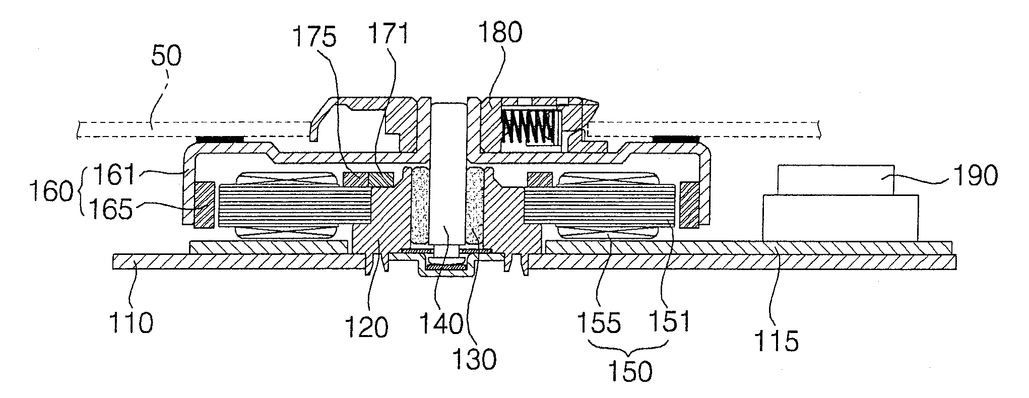
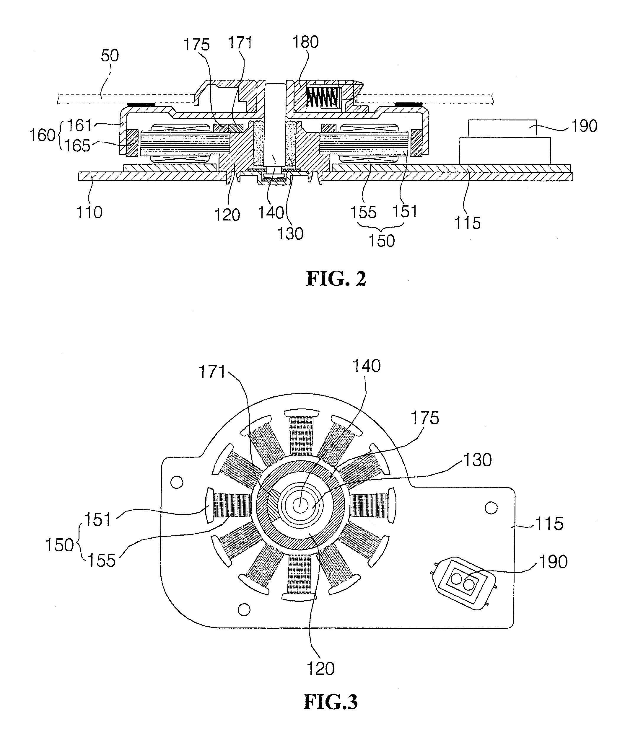
[0020]FIG. 2 is a cross-sectional view of a spindle motor according to an embodiment. FIG. 3 is a plan view of a spindle motor that removes a rotor illustrated in FIG. 2. FIG. 4 is a plan view of a spindle motor in which a rotating shaft supported in a bearing rotates according to an embodiment.

[0021]Referring to FIGS. 2 to 4, a bearing housing 120 is vertically disposed on a base 110. A bearing 130 is press-fitted into the bearing housing 120, and a lower portion of a rotating shaft 140 is rotatably supported to the bearing 130. The rotating shaft is formed of a magnetic material.

[0022]A stator 150 is fixed to the bearing housing 120, and a rotor 160 is fixed to the rotating shaft 140. The stator 150 includes a core 151 fixed to an outer peripheral surface of the bearing housing 110 and a coil 155 wound around the core 151. The rotor 160 includes a rot...


PUM


Abstract

A spindle motor is provided. The spindle motor comprises a bearing housing, a bearing, a rotating shaft, a stator around, a rotor, and a first magnet. The bearing is fixed inside the bearing housing. The rotating shaft is rotatably inserted into the bearing. The stator surrounds the bearing housing. The rotor is fixed to the rotating shaft to rotate by interaction thereof with the stator. The first magnet surrounds the rotating shaft to attract the rotating shaft in one side direction.

Description

CROSS-REFERENCE TO RELATED APPLICATION[0001]The present application claims priority under 35 U.S.C. 119(e) of Korean Patent Application No. 10-2007-0064035, filed Jun. 28, 2007, which is hereby incorporated by reference in its entirety.BACKGROUND[0002]The present disclosure relates to a spindle motor.[0003]A spindle motor is installed in an optical disk drive (ODD) in order to rotate a disk such that an optical pickup, which linearly reciprocates in the ODD, can read out data recorded on the disk.[0004]FIG. 1 is a plan view of a related art spindle motor in which a rotating shaft supported in a bearing rotates.[0005]Referring to FIG. 1, a bearing 10 press-fitted into a bearing housing (not shown) is prepared, and a rotating shaft 20 is rotatably inserted into and supported by the bearing 10.[0006]The rotating shaft 20 rotates by an interaction between a stator (not shown) and a rotor (not shown). The rotating shaft 20 rotates while the rotating shaft 20 revolves along an inner perip...

Claims


Application Information

Patent Timeline
Patent Type & Authority Applications(United States)
IPC IPC(8): H02K21/22
CPCH02K9/00H02K5/163H02K7/065H02K5/24
Inventor SONG, CHUNG HYUN
Owner LG INNOTEK CO LTD
Learn More