
Rotary electric machine

a technology of electric machines and rotary motors, applied in the direction of dynamo-electric machines, electrical equipment, supports/enclosements/casings, etc., can solve the problems of increased increased vibrations transmitted from the rotary electric machine to the outer fan duct, and increased noise. , to achieve the effect of reducing noise, reducing surface vibration of the outer fan duct, and reducing ventilation resistance in the admission

Active Publication Date: 2021-03-30
HITACHI IND PROD LTD
View PDF3 Cites 0 Cited by
  • Summary
  • Abstract
  • Description
  • Claims
  • Application Information

AI Technical Summary

Benefits of technology

The technical effect of this invention is to reduce the noise and ventilation resistance caused by surface vibrations in a rotary electric machine. By decreasing the surface vibrations of the outer fan duct, the invention aims to minimize the noise and allow for better air flow in the heat exchanger.

Problems solved by technology

However, in the rotary electric machine disclosed in Japanese Unexamined Patent Application Publication No. 2015-154583, when the air quantity of the outer fan is increased, vortices occur on the casing surface or winds blow on the casing surface, and this causes an increase in the surface vibrations of the outer fan duct.
In consequence, noise sometimes occurs.
In the case, vibrations transmitted from the rotary electric machine to the outer fan duct are also increased.

Method used


Image

  • Rotary electric machine
  • Rotary electric machine
  • Rotary electric machine

Examples


first embodiment

[0020]FIG. 1 is a first embodiment of a rotary electric machine according to an embodiment of the present invention.

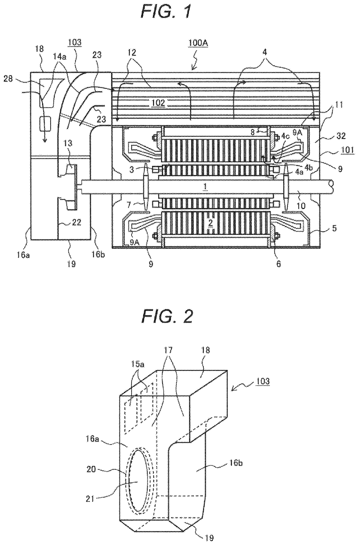
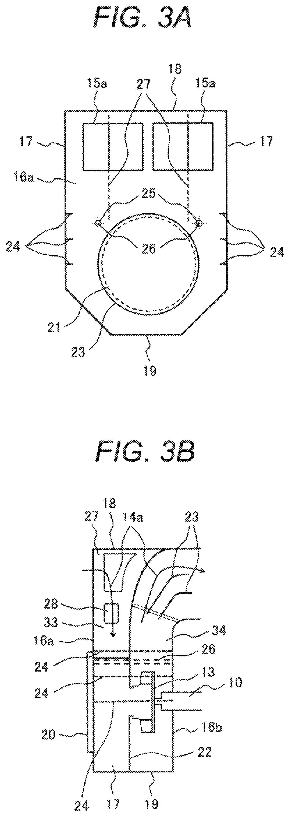
[0021]As shown in FIG. 1, a rotary electric machine 100A according to the embodiment is mainly configured of a rotary electric machine main body 101, a heat exchanger 102 that cools internal air 4 circulating in the inside of the rotary electric machine main body 101, and an outer fan duct 103 that takes outside air into the heat exchanger 102.

[0022]The rotary electric machine main body 101 includes a stator 2, a rotor 1 placed on the inner diameter side of the stator 2, the rotor 1 facing the stator 2 through an air gap 3, a stator frame 8 that supports the stator 2, a casing 11 that stores the stator 2 and the rotor 1, the heat exchanger 102 installed above the casing 11, the heat exchanger 102 being configured to exchange heat between outside air 14a taken from the outside through an outer fan 13, described later, and internal air 4 having cooled the stator 2 and th...

second embodiment

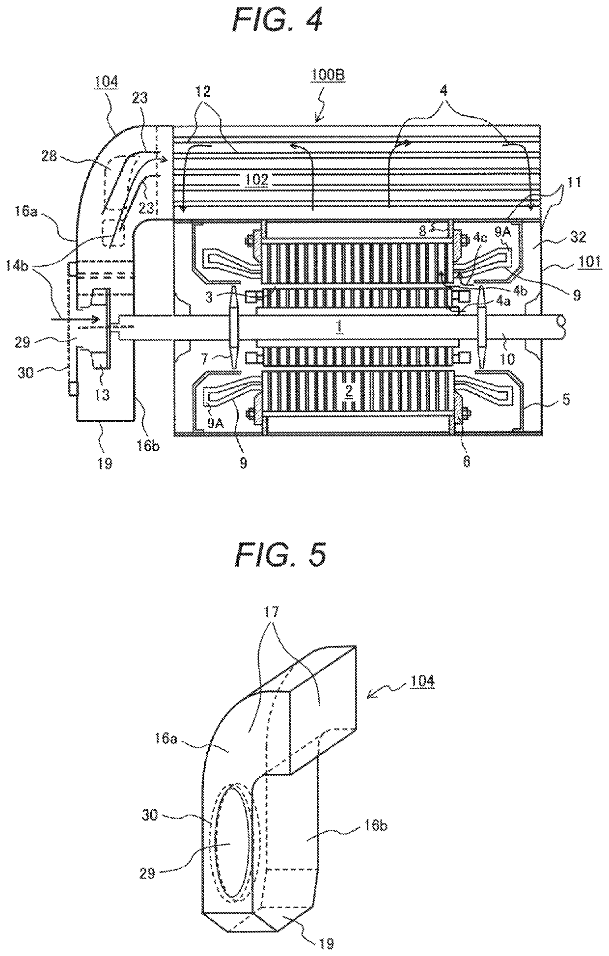
[0048]FIG. 4 is a second embodiment of the rotary electric machine according to an embodiment of the present invention.

[0049]In a rotary electric machine 100B according to the embodiment shown in FIG. 4, the mechanisms of a rotary electric machine main body 101 and a heat exchanger 102 are similar to the mechanisms of the first embodiment. However, instead of the outer fan duct 103 having two ventilation paths according to the first embodiment, one outer fan duct 104 is mounted on the rotary electric machine 100B. The outer fan duct 104 has one ventilation path suitable for the air quantity generated by an outer fan 13 and a rotary electric machine having a small number of revolutions. The outside air is taken into the heat exchanger 102 along a passage like a flow of outside air 14b.

[0050]FIG. 5 shows the outer fan duct 104 having one ventilation path according to the embodiment.

[0051]As shown in FIG. 5, the outer fan duct 104 having one ventilation path according to the embodimen...


PUM


Abstract

A rotary electric machine of the present invention includes: a stator; a rotor placed on an inner diameter side of the stator through an air gap and fixed to a rotating shaft; a stator frame supporting the stator; a casing storing the stator and the rotor; an outer fan fixed to the rotating shaft; a heat exchanger installed above the casing for heat exchange between outside air taken through the outer fan and internal air to remove heat; and an outer fan duct installed on an end portion of the casing in an axial direction, provided with the outer fan in an inside of the outer fan duct, and formed with a ventilation path through which the outside air is delivered to the heat exchanger. A plate-shaped member has at least a curved surface portion. The plate-shaped member forms the ventilation path of the outer fan duct.

Description

CLAIM OF PRIORITY[0001]The present application claims priority from Japanese Patent application serial no. 2017-248757, filed on Dec. 26, 2017, the content of which is hereby incorporated by reference into this application.BACKGROUND OF THE INVENTION[0002]The present invention relates to a rotary electric machine, and to a rotary electric machine preferable for use as one including an outer fan duct installed on the end portion of a casing in the axial direction and provided with an outer fan taking outside air into the machine, like a blower motor, a pump motor, a compressor motor, and any other motor, for example.[0003]Typically, a rotary electric machine includes a closed casing and an outer fan duct. The casing stores a stator and a rotor that configure the rotary electric machine. The outer fan duct is installed on the end portion of the casing in the axial direction. In the inside of the outer fan duct, an outer fan is provided. The outside air is taken into a heat exchanger t...

Claims


Application Information

Patent Timeline
Patent Type & Authority Patents(United States)
IPC IPC(8): H02K5/20H02K5/24H02K9/18H02K9/06H02K9/12
CPCH02K5/24H02K5/20H02K9/06H02K9/12H02K9/18H02K2205/09H02K5/207
Inventor SATO, MISATOMORI, TAKESHISUGIMOTO, KENICHIKOYAMA, TAKAYUKI
Owner HITACHI IND PROD LTD
Learn More