Steering device with variable steering ratio mechanism

a technology of steering ratio and steering device, which is applied in the direction of mechanical equipment, transportation and packaging, etc., can solve the problems of flex-spline not showing a satisfied durability and strength against torque transmission, flex-spline skip, and bring up the cost of manufacturing of flex-spline and thus that of steering device, so as to achieve the effect of reducing cos

Inactive Publication Date: 2009-01-01
FUJI KIKO CO LTD
View PDF1 Cites 13 Cited by
  • Summary
  • Abstract
  • Description
  • Claims
  • Application Information

AI Technical Summary

Benefits of technology

[0007]Accordingly, an object of the present invention is to provide a steering device with a variable steering ratio mechanism, which is free of the above-mentioned drawbacks.
[0010]Because of the above-mentioned construction of the steering device, in the present invention, there is no need of employing an element such as the cylindrical flex-spline shown in the above-mentioned publication 2000-211541. Thus, the steering device of the present invention is free of the drawbacks inevitably possessed by the flex-spline. Furthermore, because of simplicity of construction, reduction of cost is achieved by the present invention.

Problems solved by technology

However, due to its inherent construction, the flex-spline needs a quite skilled technique for production, which brings up the cost of manufacturing of the flex-spline and thus that of the steering device.
Furthermore, due to the thinner cylindrical construction, the flex-spline has failed to exhibit a satisfied durability and strength against the torque transmission.
That is, if, under cruising of a motor vehicle, an excessive external force is applied to steered road wheels in a direction to drive the same in a reversed direction, deformation of the flex-spline tends to occur which causes a teeth skip (viz., disengagement of mutual teeth) of the flex-spline relative to the pinion shaft.

Method used


Image

  • Steering device with variable steering ratio mechanism
  • Steering device with variable steering ratio mechanism
  • Steering device with variable steering ratio mechanism

Examples


first embodiment

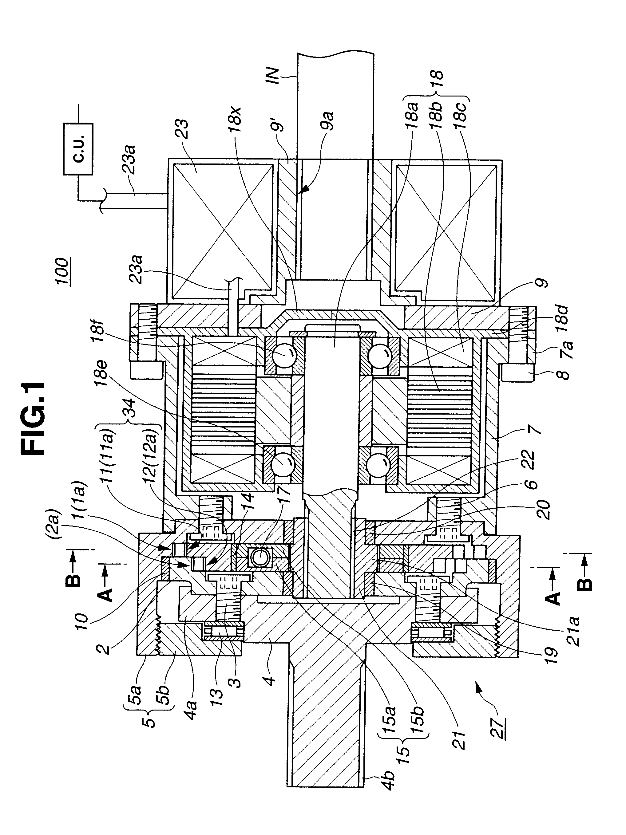
[0021]Referring to FIGS. 1 to 4B of the drawings, there is shown a steering device 100 with a variable steering ratio mechanism, which is the present invention.

[0022]As is well shown in FIGS. 1 to 3, particularly FIG. 3, the steering device 100 comprises an input gear 1 and an output gear 2 which are arranged to face to each other.

[0023]As is seen from FIG. 2 (and FIG. 3), the input gear 1 is integrally provided by a bottomed cylindrical holder body 5a. That is, as shown, the input gear 1 is constituted by internal teeth 1a formed on a cylindrical inner wall of the body 5a. The bottom of the holder body 5a is connected to an annular outer surface of a cylindrical motor holder 7 through six bolts 6 each having a hexagonal driver catch opening.

[0024]As is seen from FIGS. 2 and 3, to an annular flange 7a formed on a right end of the holder body 5a, there is connected an electric motor 18 through six bolts 8 in such a manner that a major cylindrical body of the motor 18 is neatly receiv...

second embodiment

[0063]Referring to FIGS. 5 and 6, there is shown a steering device 200 with a variable steering ratio mechanism, which is the present invention.

[0064]In the steering device 200 of the second embodiment, the above-mentioned lock device is provided for assuredly locking or stopping the rotation of the output shaft 18a of the motor 18 when the motor 18 fails to rotate.

[0065]Since the steering device 200 of this second embodiment is similar in construction to the above-mentioned steering device 100 of the first embodiment, only parts and portions that are different from those of the steering device 100 of the first embodiment will be described in detail in the following.

[0066]In this second embodiment 200, there is provided a lock device that can lock the output shaft 18a of the electric motor 18 as the need arises.

[0067]As is seen from the drawings, the right end wall 18x of the case of the motor 18 is formed with a circular opening 18g through which a right end portion of the output s...


PUM


Abstract

A first reduction ratio established between first internal teeth of an input gear and first external teeth of a first planetary gear of an annular planetary gear unit is set different from a second reduction ratio established between a second internal teeth of an output gear and second external teeth of a second planetary gear of the annular planetary gear unit. A rotation cam unit is installed in a circular opening of the annular planetary gear unit to cause, upon rotation thereof, the first and second planetary gears to make an eccentric rotation relative to a common axis of the first and second internal teeth thereby to induce a circumferential movement of a first meshed portion between the first external teeth and the first internal teeth and a second meshed portion between the second external teeth and the second internal teeth. The rotation cam unit is actuated by an electric motor.

Description

BACKGROUND OF THE INVENTION[0001]1. Field of the Invention[0002]The present invention relates in general to steering devices with a variable steering ratio mechanism and more particularly to the steering devices of a type that provides an intermediate shaft, which is connected to a steering wheel, with the variable steering ratio mechanism.[0003]2. Description of the Related Art[0004]Hitherto, various types of steering devices have been proposed and put into practical use in the field of wheeled motor vehicles. One of them is of a type equipped with a steering ratio mechanism that is able to vary a ratio of a steering wheel angle relative to a steered road wheel angle in accordance with a vehicle speed. One of the steering devices of such type is disclosed in Japanese Laid-open Patent Application (Tokkai) 2000-211541.[0005]In the steering device of the Laid-open patent application, a variable steering ratio mechanism is mounted to an intermediate shaft that connects a steering shaft...

Claims


Application Information

Patent Timeline
Patent Type & Authority Applications(United States)
IPC IPC(8): B62D5/04
CPCF16H1/32B62D5/008
Inventor IKEGAYA, ISAOITOU, TADAO
Owner FUJI KIKO CO LTD
Why Eureka
Try Eureka