Electric steam iron

a technology of electric steam and iron, which is applied in the field of electric steam irons, can solve the problems of many drops of steam being sprayed out from the bottom plate, the water cannot be fully boiled, and the efficiency of generating steam is very limited, so as to and improve the effect of boiling water

Inactive Publication Date: 2009-01-01
ZHEJIANG YUELI ELECTRICAL
View PDF13 Cites 7 Cited by
  • Summary
  • Abstract
  • Description
  • Claims
  • Application Information

AI Technical Summary

Benefits of technology

[0006]In order to improve the effect of boiling water of these two steam generators, a winding water passage which winds back and forth can be provided in the boiling chamber and the steam boiler. By increasing the distance the water must pass, the area of the water touching the steam generators is increased as well, so that the effect of boiling of the water can be improved.
[0007]In order to make a further improvement of the effect of boiling of the water, a plurality of barrier pieces can be provided on the inner walls of each water passage, to further increase the area of the water touching the steam generators.
[0008]Sometimes, impurities in the water may block the water passage, and if the steam inside the steam boiler cannot be output normally, the pressure inside the boiler becomes greater and greater, and this can be very dangerous. In order to make the steam boiler much safer, a safety valve is provided on the steam boiler, generally, on the bottom of the steam boiler. In case the pressure inside the steam boiler accidently becomes too great, the superfluous steam inside the steam boiler can be directly output through the safety valve. This makes the electric iron much safer to use.
[0009]The steam boiler is independent of the bottom plate and is not effected by the temperature of the bottom plate. It is better for the steam boiler to be completely segregated from the bottom plate. Further, there is a heat insulation cover which covers the steam boiler to segregate the steam boiler. Because of this arrangement, the steam boiler will achieve better heat insulation segregated from the bottom plate. This will reduce the interaction of these two devices, and prevent the great heat of the steam boiler from transferring to other devices in the iron. This will also reduce the temperature of the housing of the iron and the user will not be scalded when using it.
[0010]In order to better control the infusion of the water in the water tank to the steam boiler, an electromagnetic pump is provided. The inlet of the electromagnetic pump is in fluid communication with the water tank, and the outlet of the electromagnetic pump is in fluid communication with the inlet of the steam boiler. The water in the water tank is thereby input into the steam boiler through the electromagnetic pump. Moreover, a filter tip is provided at the inlet of the electromagnetic pump to filter impurities in the water and to eliminate any bad effect on the electromagnetic pump and two steam generators by the impurities.
[0011]Compared with the prior art, in the present invention, there are two independent steam generators in the electric iron. The steam boiler firstly ensures turning most of the water into steam, and then, the steam from the steam boiler will come into the boiling chamber in the bottom plate, where the steam will be further heated by the high temperature of the bottom plate. The little drops in the steam will thereby be fully boiled. This avoids the phenomenon of steam with many drops, and keeps the purity of the steam sprayed out of the bottom plate high, to guarantee the effect of good ironing. The boiling effect of the electric steam iron of the present invention is more ideal, and the steam boiler working independently can generate a great deal of steady steam. Further, the heat insulation cover between the steam boiler and the bottom plate can make the steam boiler independent from the bottom plate so that it is not effected by the temperature of the bottom plate. The structure of the present invention is simple and the actual effect of ironing is excellent, and it is easy to be manufactured.

Problems solved by technology

However, since there is only one steam generator in the known electric steam iron, and the area of the bottom plate and the power of the iron are limited, the temperature is also variational, so that the efficiency of the generating steam is very limited.
Specifically, the water cannot be fully boiled, which leads to the steam being sprayed out from the bottom plate including many drops.

Method used


Image

  • Electric steam iron
  • Electric steam iron
  • Electric steam iron

Examples


Embodiment Construction

[0017]To enable a further understanding of the innovative and technological content of the invention herein, reference is made to the detailed description of the invention and the accompanying drawings below.

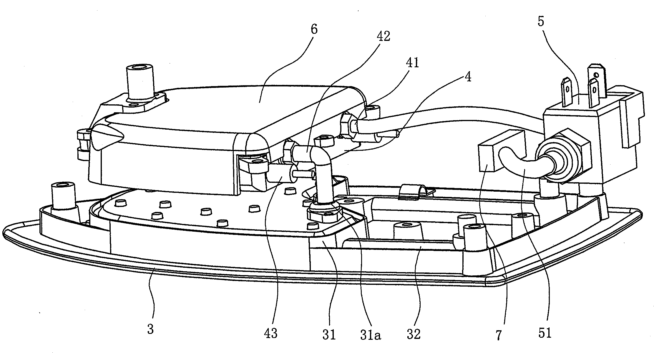
[0018]FIGS. 1˜5 show an embodiment of the present invention. In this embodiment, the electric steam iron comprises a housing (1), a water tank (2), an electromagnetic pump (5), a bottom plate (3) which has a boiling chamber (31) inside it, a heating device (32) which is used to heat the bottom plate (3), and an independent steam boiler (4) above the bottom plate (3).

[0019]The housing (1) is made up of a thin plate or many pieces of lamella as required by the actual manufacture. The water tank (2) is enclosed within the housing (1), and is formed as a closed chamber at a position higher than bottom plate (3) and steam boiler (4). This is similar to an existing open-style electric steam iron.

[0020]The water tank (2) is in fluid communication with the inlet (41) of the steam boiler...


PUM


Abstract

An electric steam iron includes a housing, a water tank within the housing, a bottom plate to which the housing is secured, a heating device in the bottom plate for heating the bottom plate, a boiling chamber inside the bottom plate, and a further independent steam boiler above the bottom plate, and having an inlet in fluid communication with the water tank and an outlet in fluid communication with the inlet of the boiling chamber, such that steam from the steam boiler will be supplied to the boiling chamber in the bottom plate and further heated by the high temperature of the bottom plate, so that little drops in the steam will be fully boiled, thereby providing a high purity of the steam sprayed out of the bottom plate.

Description

BACKGROUND OF THE INVENTION[0001]The present invention relates generally to electric irons for use in the home, and more particularly, to a more efficient electric steam iron.[0002]Known electric steam irons mainly comprise a housing, a water tank, a bottom plate and a heating device which is used to heat the bottom plate. A boiling chamber is provided inside the bottom plate, whereby the water can be heated up and boiled by the bottom plate, so that the boiling chamber in the bottom plate forms a steam generator. When the iron is working, the water in the boiling chamber is heated by the bottom plate and turns to steam, and this can then be sprayed out from the steam outlet of the bottom plate to iron the clothing. However, since there is only one steam generator in the known electric steam iron, and the area of the bottom plate and the power of the iron are limited, the temperature is also variational, so that the efficiency of the generating steam is very limited. Specifically, t...

Claims


Application Information

Patent Timeline
Patent Type & Authority Applications(United States)
IPC IPC(8): D06F75/18
CPCD06F75/24
Inventor GUOHONG, FANG
Owner ZHEJIANG YUELI ELECTRICAL
Why Eureka
Try Eureka