
Dimming algorithms based upon light bulb type

Active Publication Date: 2008-12-25
ENOCEAN
View PDF19 Cites 27 Cited by
  • Summary
  • Abstract
  • Description
  • Claims
  • Application Information

AI Technical Summary

Benefits of technology

[0005]In an aspect of this invention, a dimmer circuit is provided with controls which are able to provide a dimming control to a light which is different dependent on the bulb

Problems solved by technology

However, to date, lighting control systems have not utilized different algorithms dependent on bulb type.

Method used


Image

  • Dimming algorithms based upon light bulb type
  • Dimming algorithms based upon light bulb type
  • Dimming algorithms based upon light bulb type

Examples


Embodiment Construction

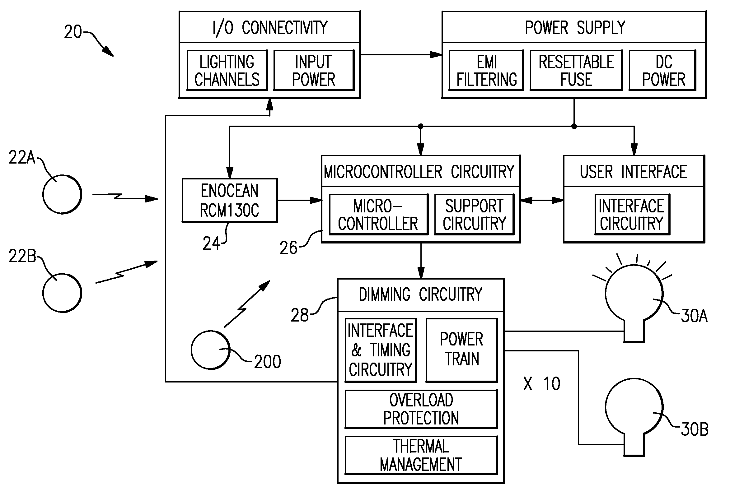
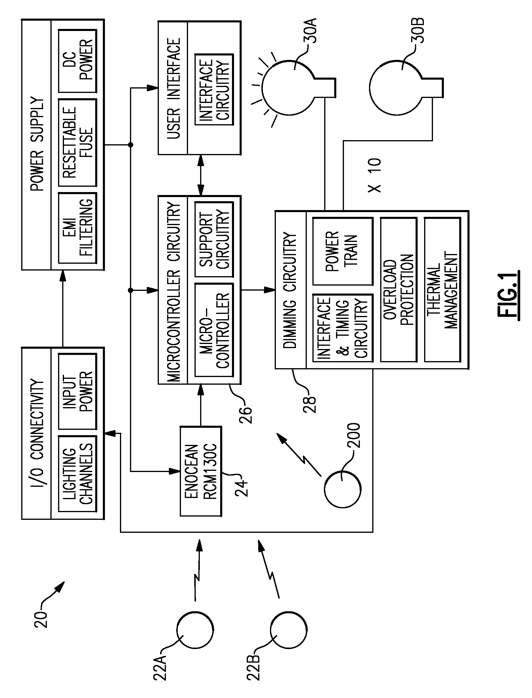
[0010]FIG. 1 shows a lighting control circuit 20 for a building. As shown, a plurality of switches 22A, 22B, etc. communicate through a wireless connection to a multi-channel receiver 24. This receiver may be as available from Enocean, and available for example under its Product No. RCM130C. The use of a wireless receiver and wireless switches are not limiting on this invention, but only mentioned as one possible type of system.

[0011]The receiver 24 communicates with a microcontroller 26, which in turn communicates with dimmer circuit 28. The dimmer circuits 28 (only one of which is shown) control the intensity of lights 30A, 30B, etc.

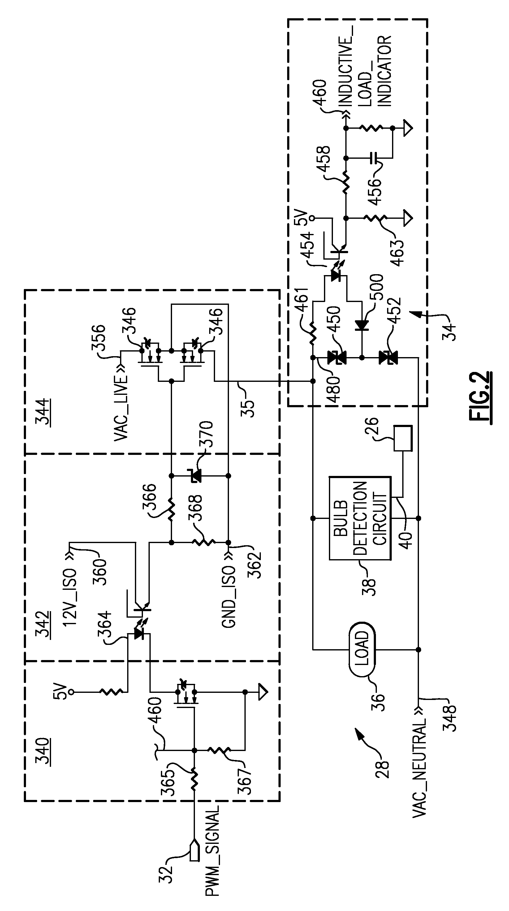
[0012]FIG. 2 schematically shows a dimmer circuit, such as the main circuitry 28 as shown in FIG. 1. A pulse width modulation control from a microcontroller, such as microcontroller 26, communicates into a dimmer circuit 28 to control the power supplied to an outlet line 35. Outlet line 35 communicates to a load 36. An inductive load sensing circuit 34...


PUM


Abstract

A lighting control circuit for dimming a light is provided with different algorithms that are utilized to dim fluorescent and incandescent lights. Some method of identifying the type of light which is to be dimmed, reports to a control for the lighting control circuit, and the appropriate algorithm is then selected and utilized.

Description

BACKGROUND OF THE INVENTION[0001]This application relates to a lighting control system including a dimmer circuit, which utilizes different algorithms dependent on the type of bulb that is being dimmed.[0002]Lighting control systems are known, and may include dimmer circuits. As known, a dimmer circuit limits the light intensity of a bulb in some manner.[0003]In modern buildings, there may be incandescent bulbs and fluorescent bulbs. Historically, residential lighting was provided more by incandescent bulbs, however, fluorescent bulbs are being mandated by government regulation.[0004]Fluorescent lights are different than incandescent lights. As an example, they light up at different rates, and have other differing characteristics. However, to date, lighting control systems have not utilized different algorithms dependent on bulb type.SUMMARY OF THE INVENTION[0005]In an aspect of this invention, a dimmer circuit is provided with controls which are able to provide a dimming control to...

Claims


Application Information

Patent Timeline
IPC IPC(8): H05B41/36H01J41/00
CPCH05B39/044H05B41/3924Y10S315/04H05B39/08H05B39/04H05B41/392
Inventor XU, JIAN
Owner ENOCEAN
Learn More