
Apparatus for Producing Ic Chip Package

a technology of ic chip and apparatus, applied in the direction of conveying, transportation and packaging, pile separation, etc., can solve the problems of difficult to increase the speed large space requirements, and long application of pressure and heat, so as to improve the reliability of apparatus, improve efficiency of ic chip package production, and improve the effect of apparatus reliability

Inactive Publication Date: 2008-12-18
SINFONIA TECHNOLOGY CO LTD
View PDF7 Cites 19 Cited by
  • Summary
  • Abstract
  • Description
  • Claims
  • Application Information

AI Technical Summary

Benefits of technology

[0011]In light of the above problems, a first object of this invention is to provide an IC chip package production apparatus which produces IC chip packages at high speed, and which can stabilize the IC chip mounting position.
[0012]A second object of this invention is to provide an IC chip package production apparatus which reduces the space dedicated to the mechanism for application of heat and pressure.

Problems solved by technology

However, the above apparatuses for producing IC chip packages of the prior art have the following problems.
Hence it is difficult to increase the speed of production of IC chip packages.
Further, when the circuit sheets or IC chips are affixed while continuously conveying the base sheet or film substrate, because a substantial amount of time is necessary to perform thermal pressure bonding of the base sheet or film substrate and the circuit sheet or IC chip using the anisotropic conductive adhesive, the mechanism for application of pressure and heat must be very long, so that much space is required.

Method used


Image

  • Apparatus for Producing Ic Chip Package
  • Apparatus for Producing Ic Chip Package
  • Apparatus for Producing Ic Chip Package

Examples


first embodiment

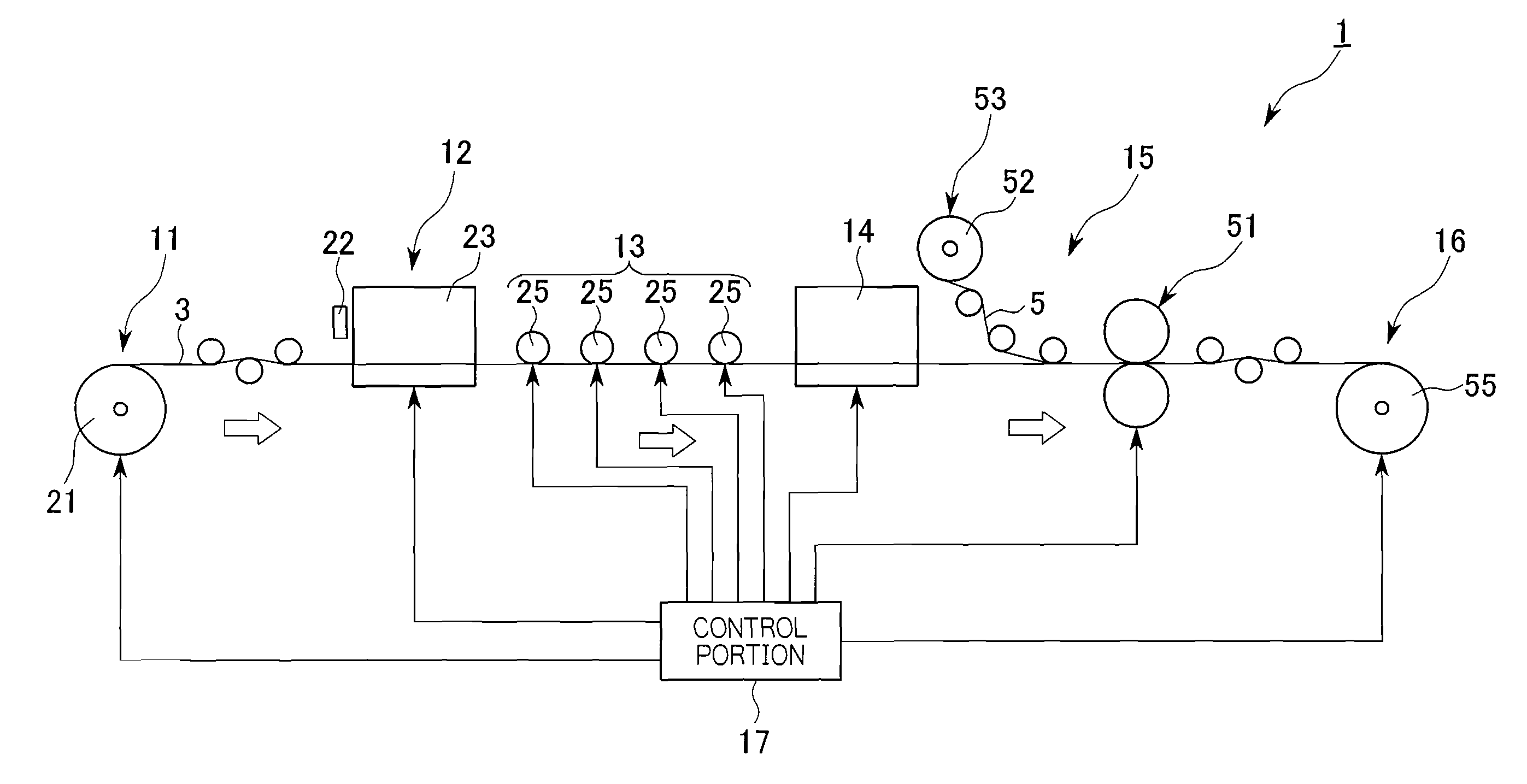
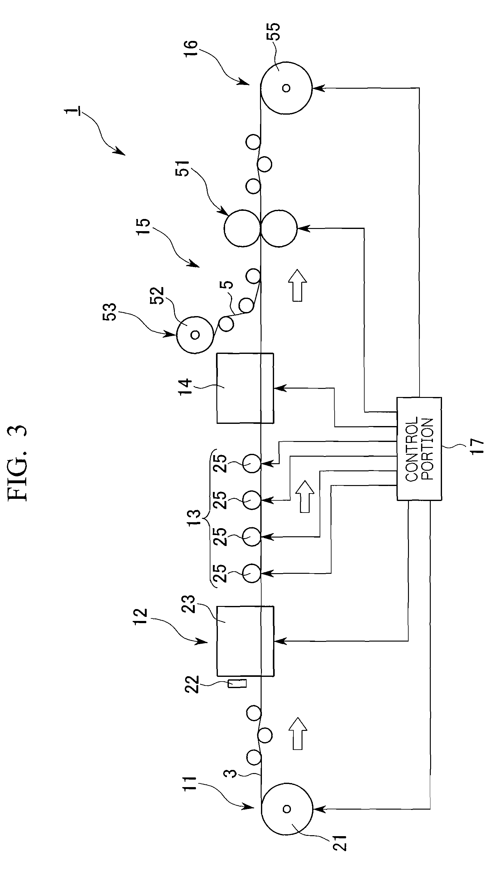
[0067]Below, a first embodiment of an IC chip package production apparatus of the invention is explained, referring to FIG. 1 through FIG. 9.

[0068]An IC chip package production apparatus 1 of this embodiment is a production apparatus which for example produces, as IC chip packages, ID tags 2.

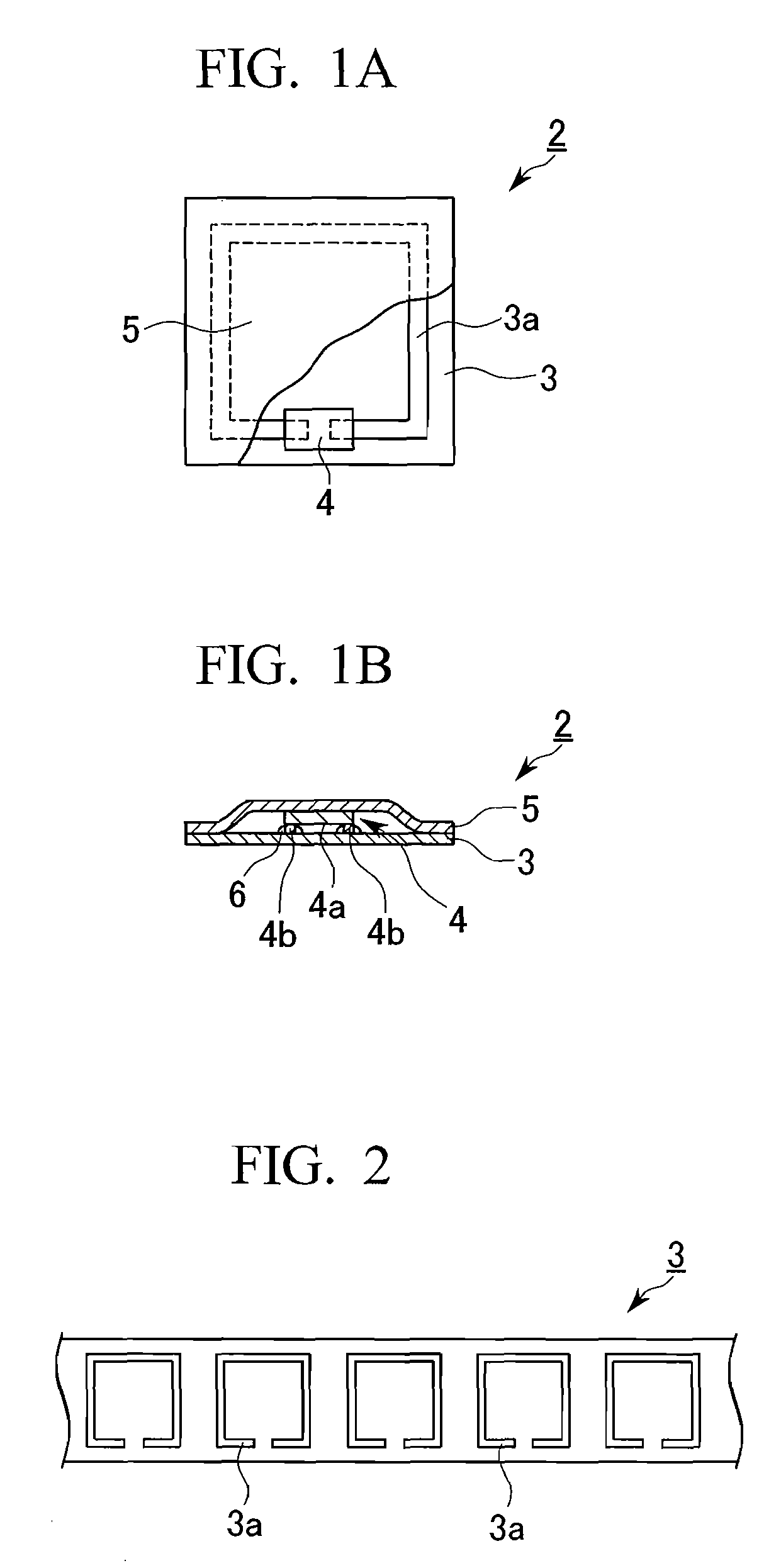
[0069]As shown in FIG. 1, these ID tags 2 comprise a film substrate 3 on which is formed an antenna circuit 3a in a prescribed position, an IC chip 4 mounted in a prescribed position on the antenna circuit 3a, and a cover sheet 5.

[0070]The antenna circuit 3a is formed in advance on the film substrate 3 by a printing technique and etching, and as shown in FIG. 2, is formed continuously at equal intervals on the film substrate 3.

[0071]The IC chips 4 are provided on the bottom face 4a with bumps 4b, formed for example from silver or gold, to enable connection to the antenna circuits 3a, which are connected to the antenna circuits 4a via an adhesive 6 formed for example from an anisotropic conductiv...

second embodiment

[0145]Next, the IC chip package production apparatus of a second embodiment of the invention is explained, referring to FIG. 15 through FIG. 20.

[0146]As shown in FIG. 15, the IC chip package production apparatus 201 of the second embodiment comprises a film substrate accommodation portion 211, which accommodates film substrate 3; an IC chip mounting portion 212, which mounts IC chips 4 at prescribed positions on the film substrate 3; a thermal pressure-bonding portion 213, which performs thermal pressure-bonding of IC chips 4 and the film substrate 3; a product take-up portion 214, which takes up the film substrate 3 on which are mounted the IC chips 4; and, a control portion 215 which controls these portions.

[0147]The film substrate accommodation portion 211 accommodates a roll 216 of the film substrate 3 shown in FIG. 2, and is controlled by the control portion 215 such that the film substrate 3 moves at a fixed velocity and is under a fixed tension. Film substrate 3 fed from this...


PUM


Abstract

An IC chip package production apparatus of this invention comprises a conveyance portion which conveys a film substrate, and an IC chip mounting portion which mounts IC chips on the film substrate. The IC chip mounting portion comprises a mounting roller, on the outer face of which are formed a chip holding groove and a suction-clamping hole, which mounts IC chips on the film substrate by holding IC chips and rotating; an IC chip supply portion, having a supply path which supplies a plurality of IC chips successively; and a linear feeder which, with one supply end of the supply path opposing the chip holding groove and suction-clamping hole, feeds IC chips from the supply end to the chip-holding groove. The production apparatus further comprises a thermal pressure-bonding portion which performs thermal pressure-bonding of IC chips and the film substrate; this thermal pressure-bonding portion has a tape with magnets and a magnetic tape on the conveyor path conveying the film substrate, which apply pressure to the film substrate on the conveyor path without stopping the motion, and a heat-application portion which applies heat to the film substrate on the conveyor path without stopping the motion.

Description

TECHNICAL FIELD[0001]This invention relates to an apparatus for producing IC chip packages such as, for example, ID tags.[0002]Priority is claimed on Japanese Patent Application No. 2004-188115, filed Jun. 25, 2004; Japanese Patent Application No. 2004-354069, filed Dec. 7, 2004; and Japanese Patent Application No. 2005-67589, filed Mar. 10, 2005, the entire contents of which are incorporated herein by reference.BACKGROUND ART[0003]Recently, IC chip packages called RFID (Radio Frequency Identification) cards have appeared. These cards have internal memory and a small antenna, and by exchanging information with a reader antenna in a contact-free manner, can record necessary information in memory, and are capable of rapid recording, overwriting, and reading of information with a reader / writer or other communication equipment as necessary.[0004]As an apparatus for producing IC chip packages such as these RFID cards, an apparatus has been proposed which conveys by means of a conveyor a ...

Claims


Application Information

Patent Timeline
IPC IPC(8): B66C17/08B65H1/00H01L21/677B65H1/28
CPCH01L21/67132Y10T156/17H01L24/75H01L24/83H01L2224/13099H01L2224/83192H01L2224/8385H01L2924/01002H01L2924/01004H01L2924/01005H01L2924/01029H01L2924/01033H01L2924/01047H01L2924/01051H01L2924/01079H01L2924/01082H01L2924/07802H01L2924/0781H01L2924/14H01L2924/01006H01L2924/01021H01L2224/16225H01L2924/00013H01L24/16H01L2924/07811H01L2224/29099H01L21/67144H01L2224/75651H01L2224/75745H01L2924/00011H01L2924/00014H01L2224/0401H01L2224/75611H01L2224/75621
Inventor INOUE, TAICHIMORITA, MASASHI
Owner SINFONIA TECHNOLOGY CO LTD
Learn More