Triple-band antenna and electronic device thereof
a technology of antenna and electronic device, applied in the field of antenna, can solve the problems of design needs to compromise between volume and reception efficiency, standard signal frequency antennas are now insufficient, and the effect of increasing the low frequency bandwidth
- Summary
- Abstract
- Description
- Claims
- Application Information
AI Technical Summary
Benefits of technology
Problems solved by technology
Method used
Image
Examples
first embodiment
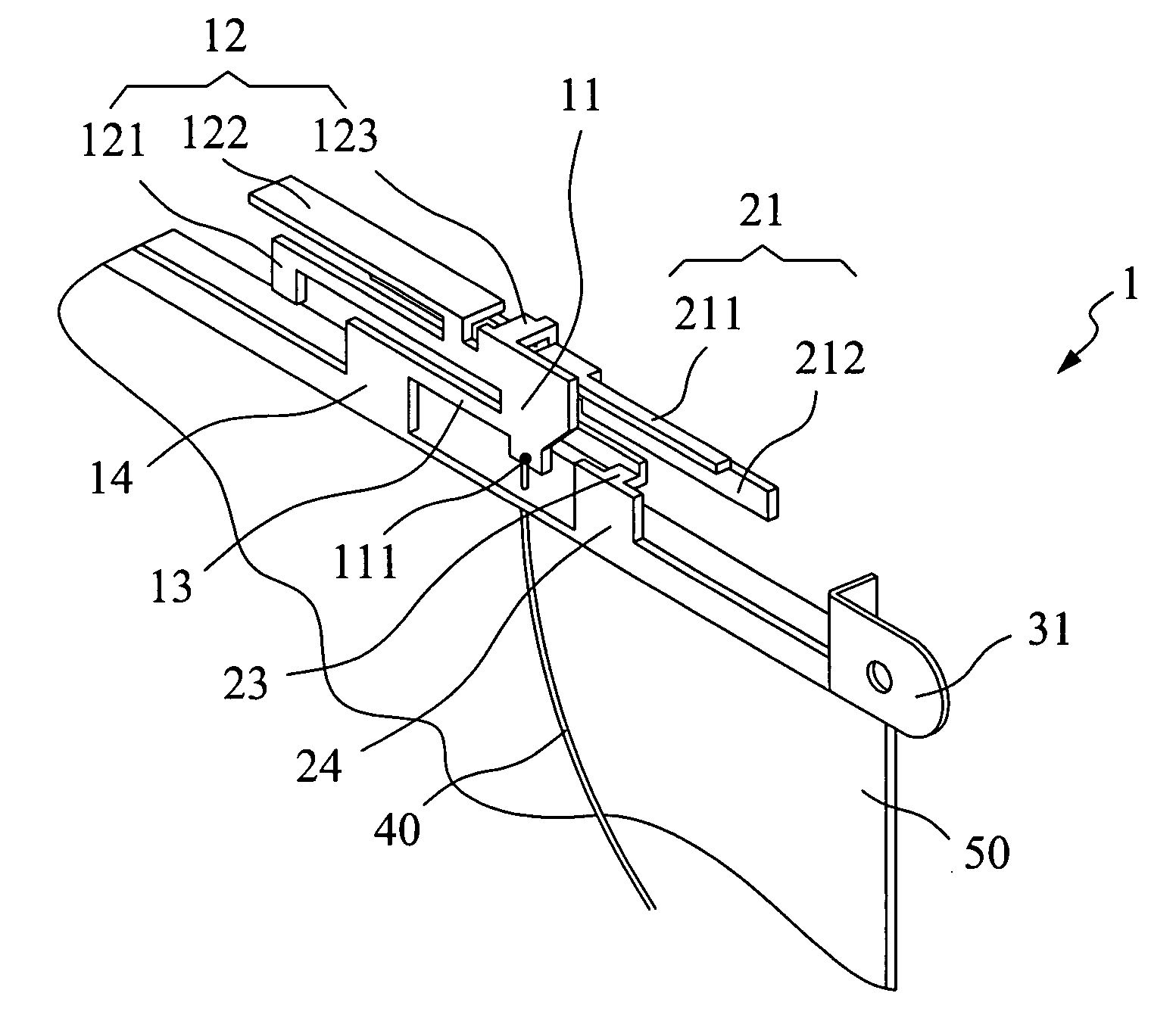
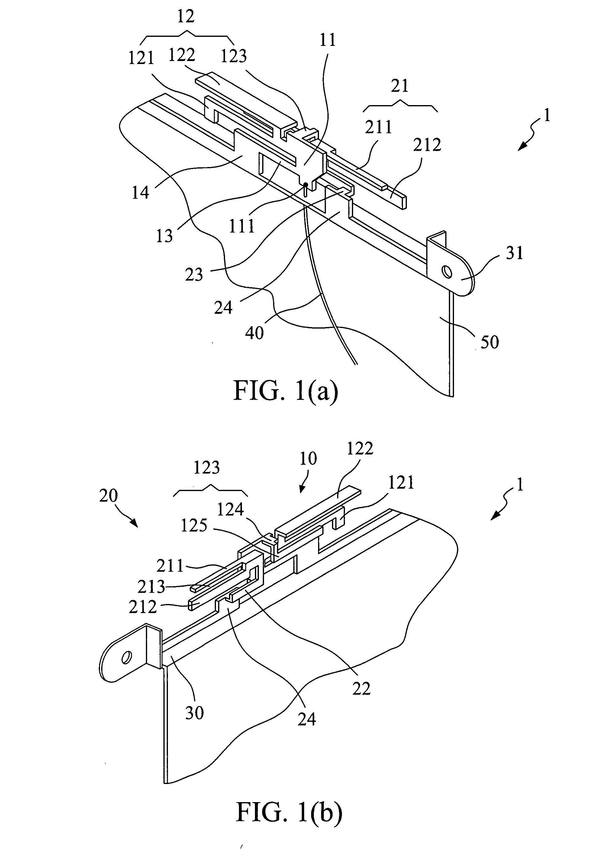
[0023]Please refer to FIGS. 1(a), (b). FIGS. 1(a), (b) are front and back view drawings of the present invention. As shown in FIGS. 1(a), (b), a triple-band antenna 1 of the present invention comprises a first radiating body 10, a second radiating body 20 and a signal feed source 40. The first radiating body 10 comprises a first metal element 11, a first radiating unit 12, a first connecting element 13 and a first grounded wall 14. The first metal element 11 comprises a feed point 111. The first metal element 11 is connected to the first radiating unit 12, and the first radiating unit 12 substantially extends along a first direction. One end of the first connecting element 13 is connected to the first metal element 11, and the other end is connected to the first grounded wall 14. The second radiating body 20 partially overlaps the first radiating body 10 and has no contact thereto, which reduces the entire volume of the triple-band antenna 1. The second radiating body 20 comprises a...
second embodiment
[0031]Please refer to FIG. 4. FIG. 4 shows voltage standing wave ratio (VSWR) measurement results of the As shown in FIG. 4, at the low frequency band from 2.3 GHz to 2.7 GHz, the intermediate frequency band from 3.3 GHz to 3.8 GHz, and the high frequency band from 5 GHz to 6 GHz, the triple-band antenna 1a has a VSWR value that is smaller than 2, and so the triple-band antenna 1a can provide broadband functions in low, intermediate, and high frequency bands. In this embodiment, a bandwidth of the low frequency band can reach to about 450 MHz, which enhances the functionality of the low frequency broadband band.
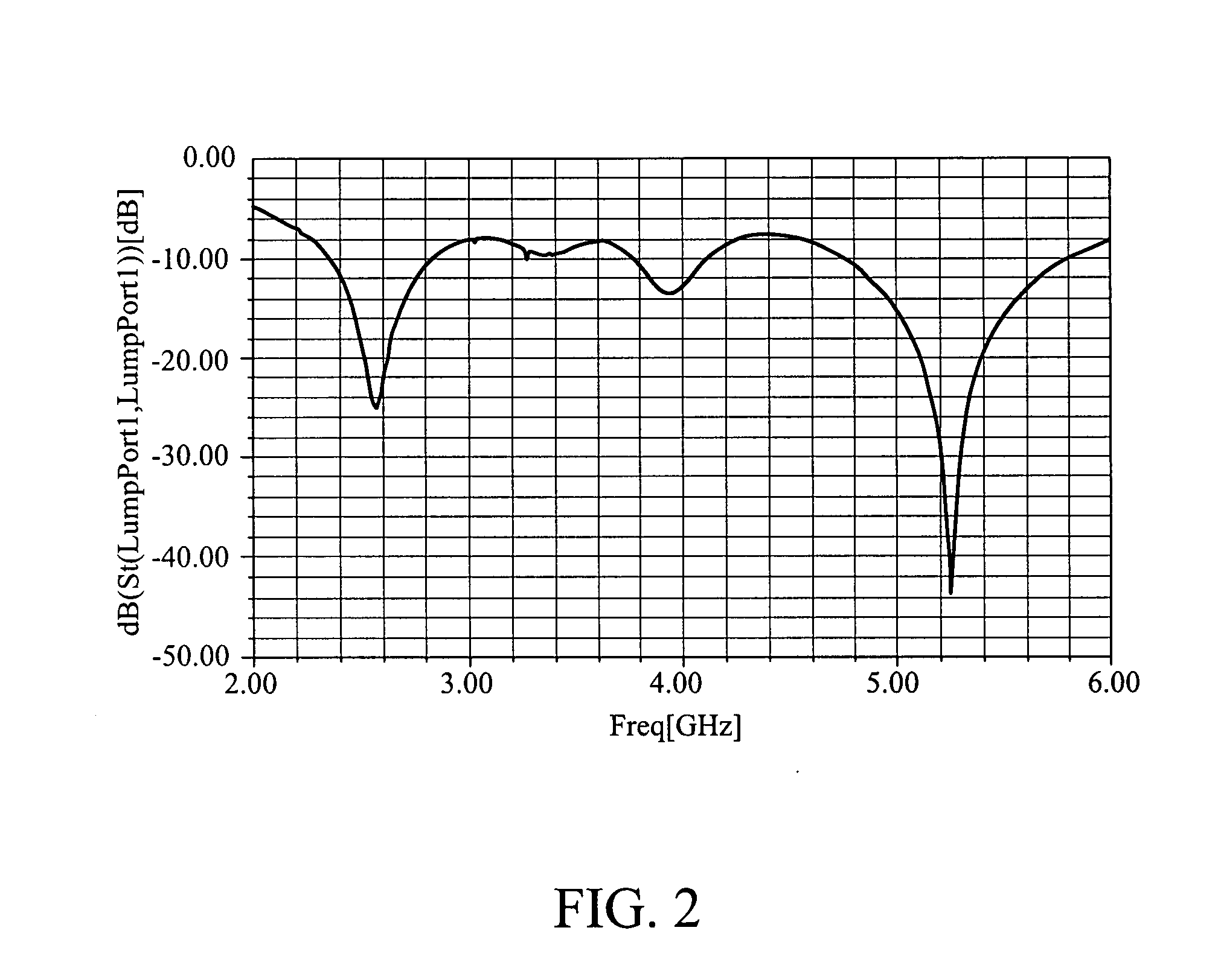
[0032]Please refer to FIG. 5 and FIG. 6. FIG. 5 is a back view drawing of a third embodiment of the present invention. FIG. 6 is a drawing showing return loss measurement results of the third embodiment of the present invention. As shown in FIG. 5, compared to the triple-band antenna 1a in the second embodiment, in a third embodiment of the present invention the rectangular ...
PUM
 Abstract
Description
Claims
Application Information
 - R&D Engineer
- R&D Manager
- IP Professional
- Industry Leading Data Capabilities
- Powerful AI technology
- Patent DNA Extraction
Browse by: Latest US Patents, China's latest patents, Technical Efficacy Thesaurus, Application Domain, Technology Topic, Popular Technical Reports.
© 2024 PatSnap. All rights reserved.Legal|Privacy policy|Modern Slavery Act Transparency Statement|Sitemap|About US| Contact US: help@patsnap.com


