
System and method for determining crosswinds

Active Publication Date: 2008-12-04
RAYTHEON CO
View PDF8 Cites 21 Cited by
  • Summary
  • Abstract
  • Description
  • Claims
  • Application Information

AI Technical Summary

Benefits of technology

The invention is a method and system for measuring crosswinds using a wavefront imager to detect variations in optical wavefronts caused by perturbations in an optical path. The method involves sending a laser signal along a signal path and receiving a response from the signal path at different times. The responses are then sorted into range gate bins and correlated to determine the crosswind direction and magnitude. The technical effects of the invention include improved accuracy and efficiency in measuring crosswinds and improved reliability in determining wind direction and speed.

Problems solved by technology

However measuring devices that utilize this principle require collecting data in many directions in a very short period of time and large amounts of computing power to approximate the three-dimensional wind velocity field.

Method used


Image

  • System and method for determining crosswinds
  • System and method for determining crosswinds
  • System and method for determining crosswinds

Examples


Embodiment Construction

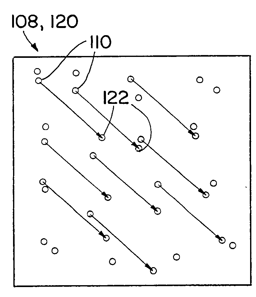
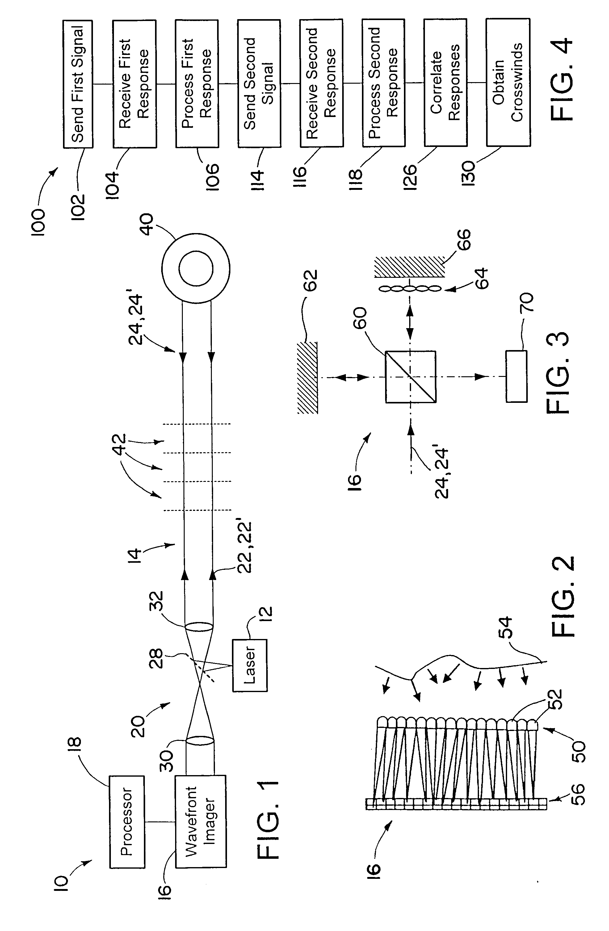
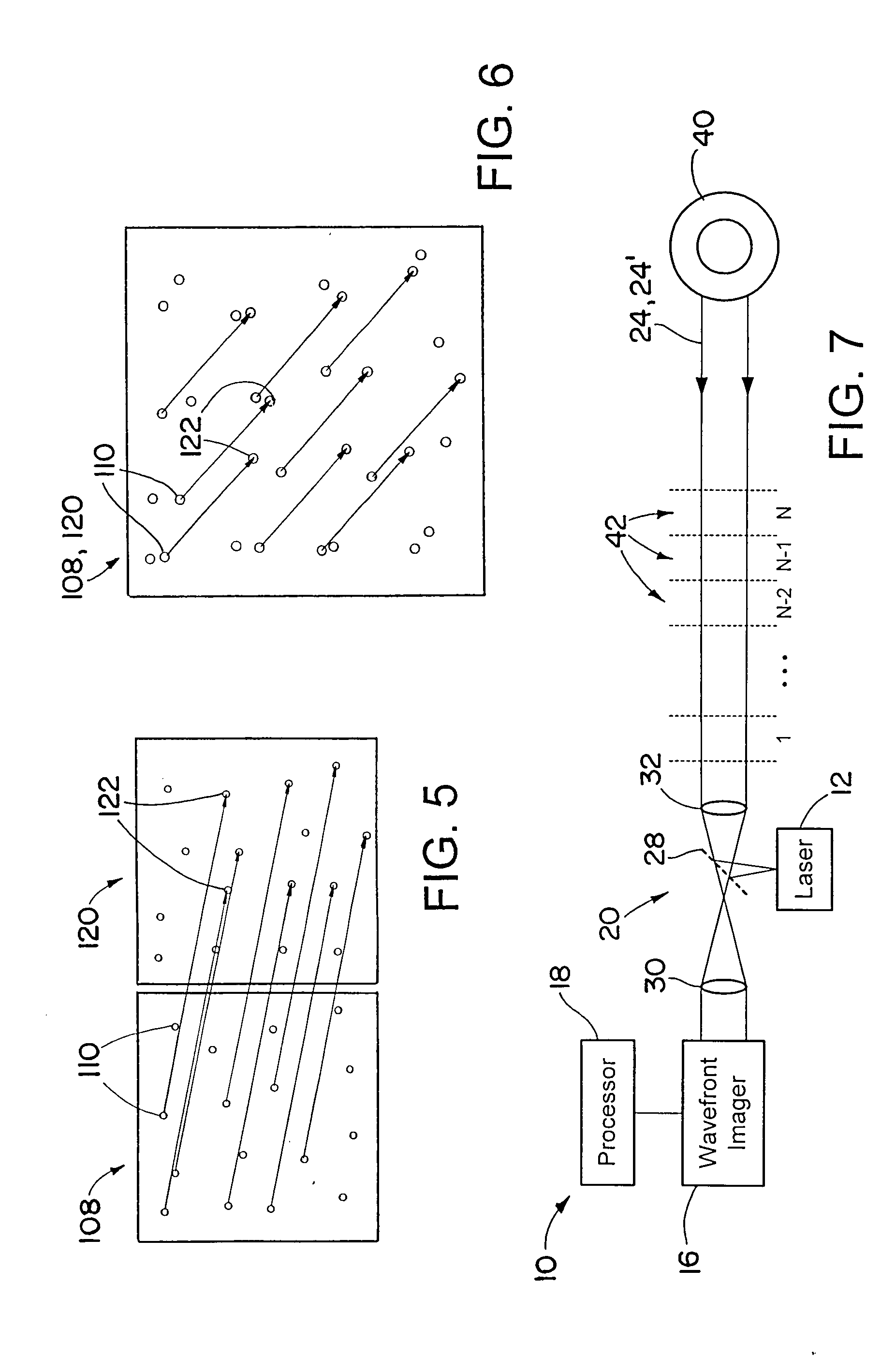
[0021]A system and method for measuring crosswinds includes using a laser to send a signal on a signal path, and receiving response signals backscattered off of aerosols or other materials in the atmosphere along the signal path. Wavefronts of the received responses are perturbated by thermal cell turbulence in the atmosphere. The thermal cell turbulence perturbs optical wavefront propagation of the outgoing signals and the returning response signals. The response signals are received by a wavefront imager, which records or measures the perturbations in the optical wavefront. Signals backscattered by airborne aerosols at different distances from the laser in the wavefront imager arrive at different times at the wavefront imager. Thus the wavefront perturbations vary with range, and data on the perturbed wavefront may be collected by the wavefront imager. A second signal may be sent back by the laser, with a second response received by the imager. Crosswinds (winds and wind component...


PUM

PropertyMeasurementUnit
distanceaaaaaaaaaa
wavelengthaaaaaaaaaa

Abstract

A system and method for measuring crosswinds includes using a laser to send a signal on a signal path, and receiving response signals backscattered off of aerosols or other materials in the atmosphere along the signal path. Wavefronts of the received responses are perturbated by thermal cell turbulence in the atmosphere that perturbs optical wavefront propagation. Signals backscattered by airborne aerosols at different distances from the laser in the wavefront imager arrive at different times at the wavefront imager. Thus the wavefront perturbations vary with range, and data on the perturbed wavefront may be collected by the wavefront imager. Crosswinds cause movements in the optical perturbations over time, as the thermal cell turbulence moves. By comparing wavefronts of signals sent at different times an amount of thermal cell displacement may be determined at a series of ranges away from the laser and the wavefront imager.

Description

BACKGROUND OF THE INVENTION[0001]1. Technical Field of the Invention[0002]The invention is in the general field of wind speed determination devices and methods.[0003]2. Description of the Related Art[0004]It is known to measure wind along a line of sight by use of the Doppler effect on radar, ladar, or acoustic signals. Wind speed in the direction along the line of sight changes the frequency of a return signal from that of an emitted signal. The magnitude of the frequency change may be used to determine the wind speed in the direction in which the signal was sent (and in which the return signal was received).[0005]Attempts have been made to measure wind in multiple directions by sending signals in multiple directions, and using the Doppler effect to determine wind speed in each of the directions. Using the wind speed in these multiple directions a calculation can be made to approximate the wind velocity in three-dimensional space around a measuring device. However measuring devices...

Claims


Application Information

Patent Timeline
Patent Type & Authority Applications(United States)
IPC IPC(8): G01C3/08G01N21/00G01P3/36
CPCG01P5/001G01P5/20G01P5/26G01P13/02G01S17/50G01S17/95Y02A90/10
Inventor CROWE, DEVON G.
Owner RAYTHEON CO
Learn More