Toric sulcus lens

a technology of toric sulcus and lens, applied in the field of toric sulcus lens, can solve the problem of not allowing the optic to touch the toric sulcus-placed non-accommodating lens

Inactive Publication Date: 2008-11-20
C& C VISION INT
View PDF74 Cites 47 Cited by
  • Summary
  • Abstract
  • Description
  • Claims
  • Application Information

AI Technical Summary

Benefits of technology

[0005]An object of this invention is to provide a “piggyback” cylindrical (toric) intraocular lens that can be placed in front of an intraocular lens that is already in the capsular bag. The lens is placed in the sulcus, which leaves a significant space between the two lenses, particularly if the lens in the capsular bag is vaulted backwards.

Problems solved by technology

These accommodating lenses vault posteriorly within the eye and move forward to accommodate; however, their forward movement at its maximum would not allow the optic to touch the toric sulcus-placed non-accommodating lens.

Method used


Image

  • Toric sulcus lens
  • Toric sulcus lens
  • Toric sulcus lens

Examples


Embodiment Construction

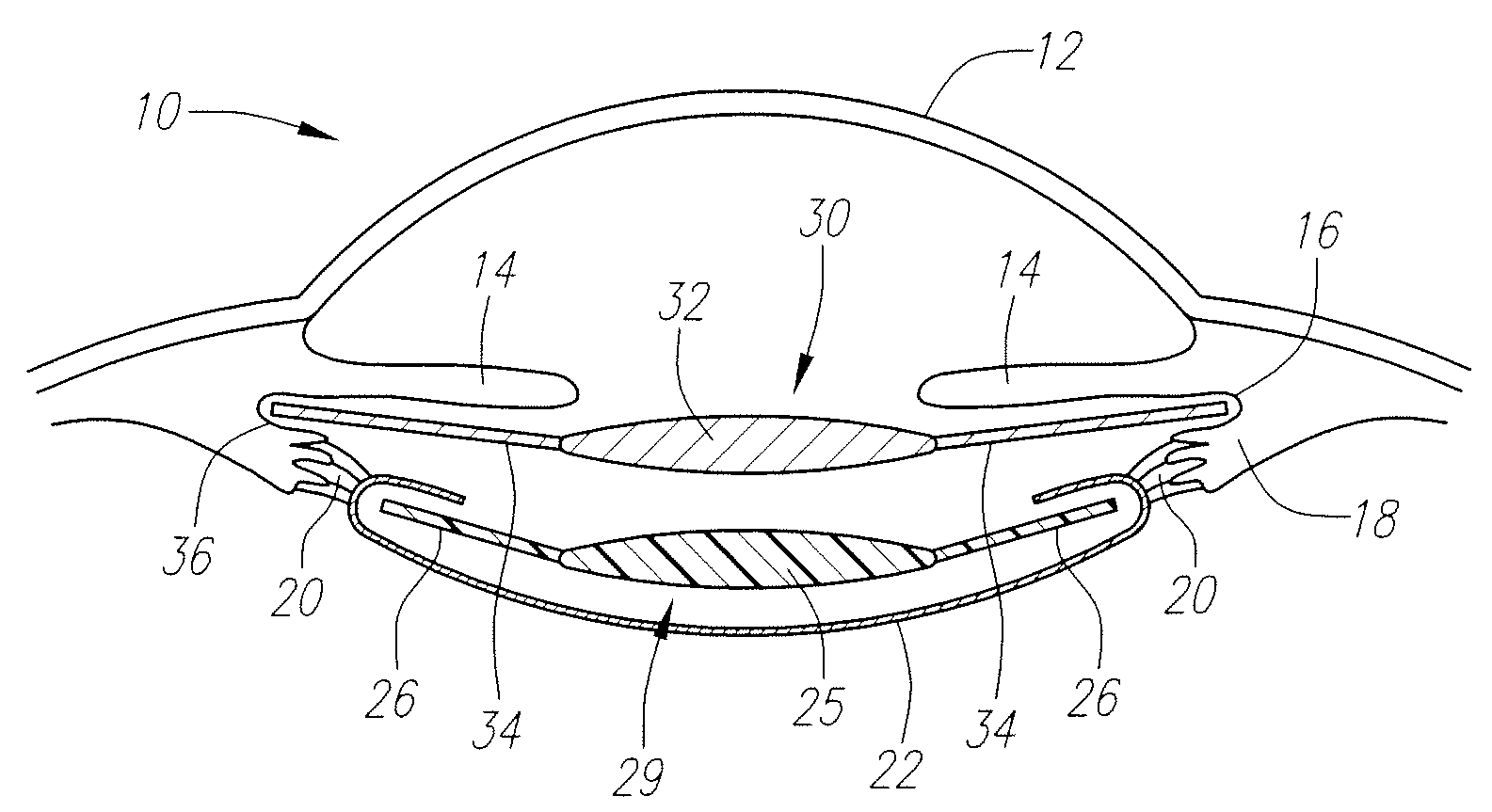
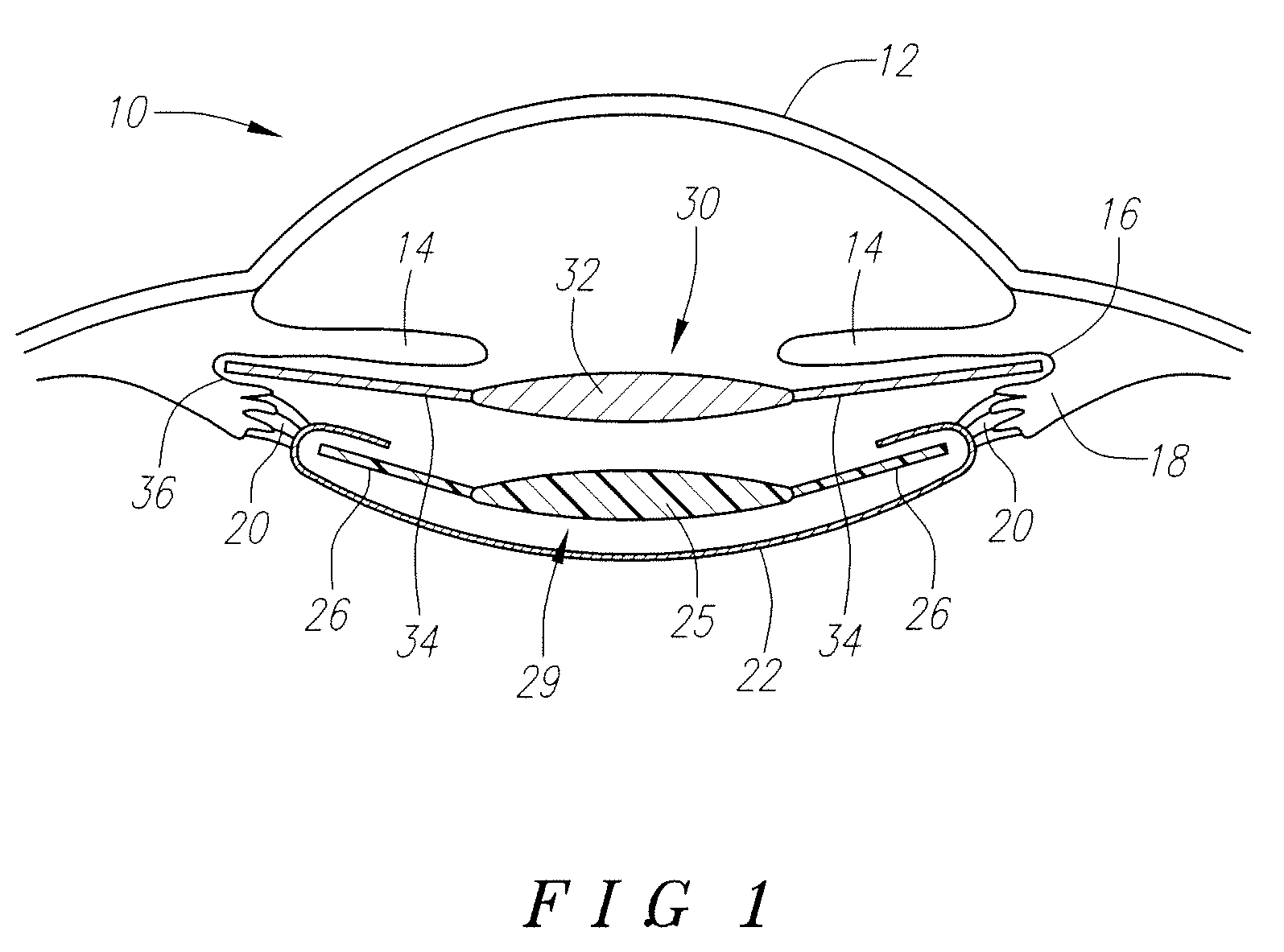
[0012]Turning now to the drawings and first to FIG. 1, the same provides cross-sectional view of the human eye 10 showing part of its structure including the cornea 12, iris 14, sulcus 16, ciliary muscle 18, zonules 20, and capsular bag 22. A standard accommodating IOL or standard IOL 24 is shown implanted in the capsular bag and having a lens 25 and haptics 26. This lens 25 can be an accommodating or standard IOL.

[0013]The improvement according to the present invention is implantation of the “piggyback” lens as described above which is identified as 30 in FIG. 1 and is a sulcus toric lens having an optic 31, haptics 34 and fixation loops 36 (only the left one being shown) on the ends of the haptics 34.

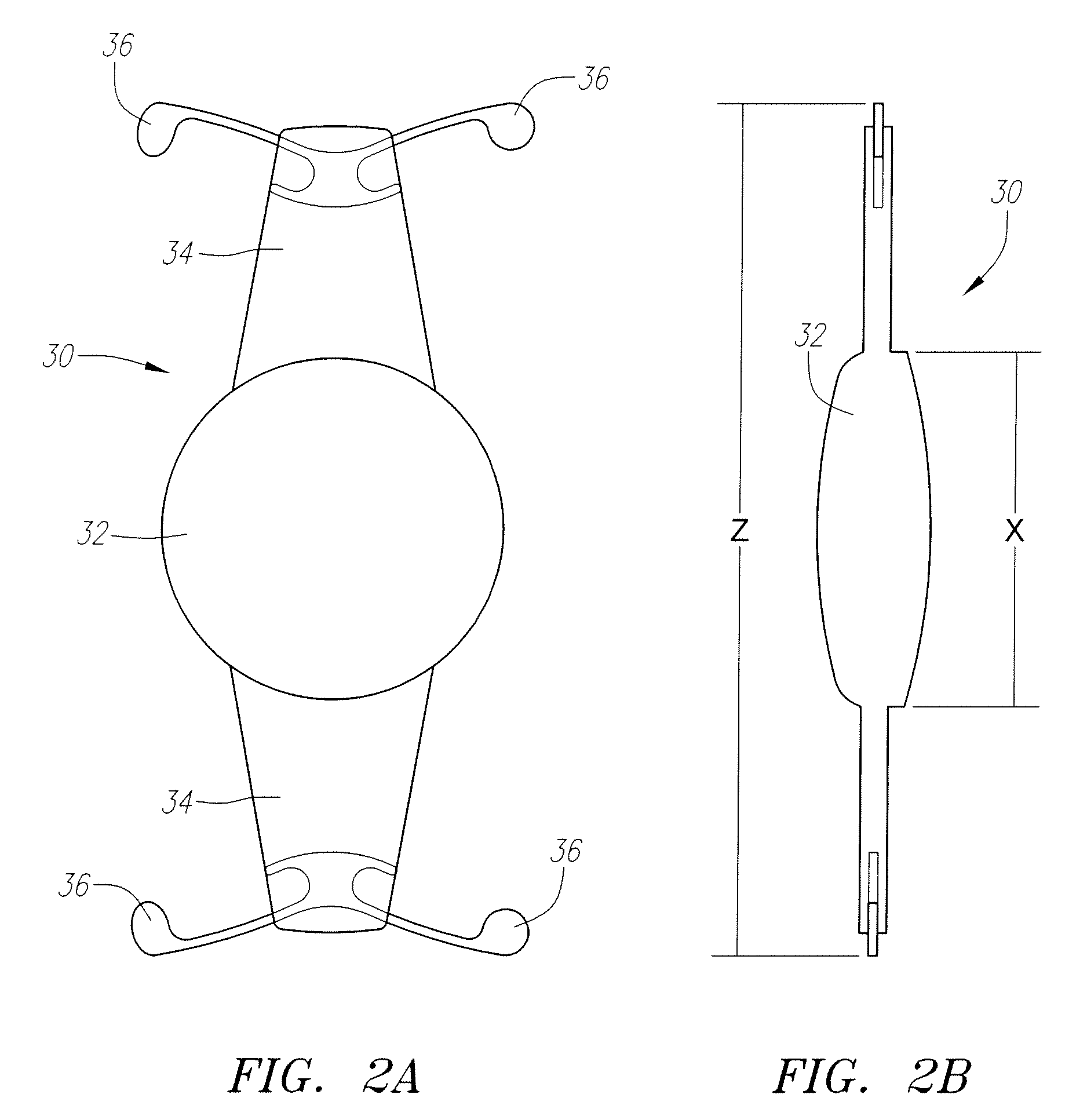
[0014]FIGS. 2a and 2b further illustrate the structure of the piggyback lens 30 showing the optic 32, haptics 34 and fixation loops 36 in further detail in FIG. 2a. The lens 30 does not have hinges like accommodating lenses. FIG. 2b is a side view to illustrate the dimension of the di...


PUM

PropertyMeasurementUnit
diameteraaaaaaaaaa
diameteraaaaaaaaaa
diameteraaaaaaaaaa

Abstract

There is disclosed herein a “piggyback” cylindrical (toric) intraocular lens for placement in front of an accommodating or standard intraocular lens that is already in the capsular bag of the eye. This additional lens is placed in the sulcus, which leaves a significant space between the two lenses, particularly if the lens in the capsular bag is vaulted backwards.

Description

[0001]This application is based on U.S. Provisional application Ser. No. 60 / 938,412 filed May 156, 2007, which is fully incorporated herein by reference.BACKGROUND[0002]The power of intraocular lenses can now, after careful preoperative measurements of the eye's length and the curvature of the cornea, be calculated to give the patient excellent vision providing they do not have astigmatism. Astigmatism is usually caused by the cornea being aspherical, having two different radii.[0003]Various methods have been used to correct the asphericity, called the corneal cylinder. These have been primarily efforts to flatten the cornea by making cuts in the cornea, so-called limbal relaxing incisions. Other surgical techniques have been performed by either intralameller surgical ablation (LASIC) or surface corneal ablation (PRK). Intraocular lenses have also been employed to correct corneal cylinder. The most common form of correction is to place a cylindrical surface on the intraocular lens. ...

Claims


Application Information

Patent Timeline
Patent Type & Authority Applications(United States)
IPC IPC(8): A61F2/16
CPCA61F2/1602A61F2/1645A61F2/164A61F2/16G02B1/04
Inventor CUMMING, J. STUART
Owner C& C VISION INT
Why Eureka
Try Eureka