Broadcast receiver having integrated spectrum analysis

Inactive Publication Date: 2008-11-20
NUCOMM
View PDF9 Cites 18 Cited by
  • Summary
  • Abstract
  • Description
  • Claims
  • Application Information

AI Technical Summary

Benefits of technology

[0018]In another aspect, the present invention comprises a system for aligning a radio antenna for a radio frequency broadcast signal, comprising: a receiver operable to receive the radio frequency signal and to produce an intermediate frequency signal having a frequency of approximately 800 MHz from the radi

Problems solved by technology

Once in the digital mode it is typically impossible to detect the presence of an adjacent channel transmitter that may cause interference until the picture starts to breakup or the BER deteriorates.
By then, however, it is usually too late.
In general, there are no tools currently available to adequately assist the operator in diagnosing link reliability issues in the digital mode.
Such problems are incorrect modulation type of the transmitter or co-channel interference.
The architecture of FIG. 1 has not, however, proven to be optimal for diagnosing the majority of link conditions that lead to link failure or reduce link reliability.
A reason the aforementioned architecture is flawed is that many problems cannot be detected after filtering and after AGC amplification.
Specifically, most interfering signals cannot be detected unless the transmitter is placed into standby mode, which results in the inability to see some types of adjacent or co-channel interference.
Furthermore, when the transmitter is placed in standby mode, it is also very difficult to diagnose link problems because the AGC circuit in the receiver brings the noise floor or interference up to a level similar to the desired signal thereby disguising the real problem.
This can cause operators or maintenance personnel to become confused and further complicate their job.
But this architecture is relatively expensive as it duplicates the LNA and synthesizer circuitry.
This method may also reduce the receiver's sensitivity because power intended for the receiver will be diverted to the spectrum analyzer.

Method used


Image

  • Broadcast receiver having integrated spectrum analysis
  • Broadcast receiver having integrated spectrum analysis
  • Broadcast receiver having integrated spectrum analysis

Examples


Embodiment Construction

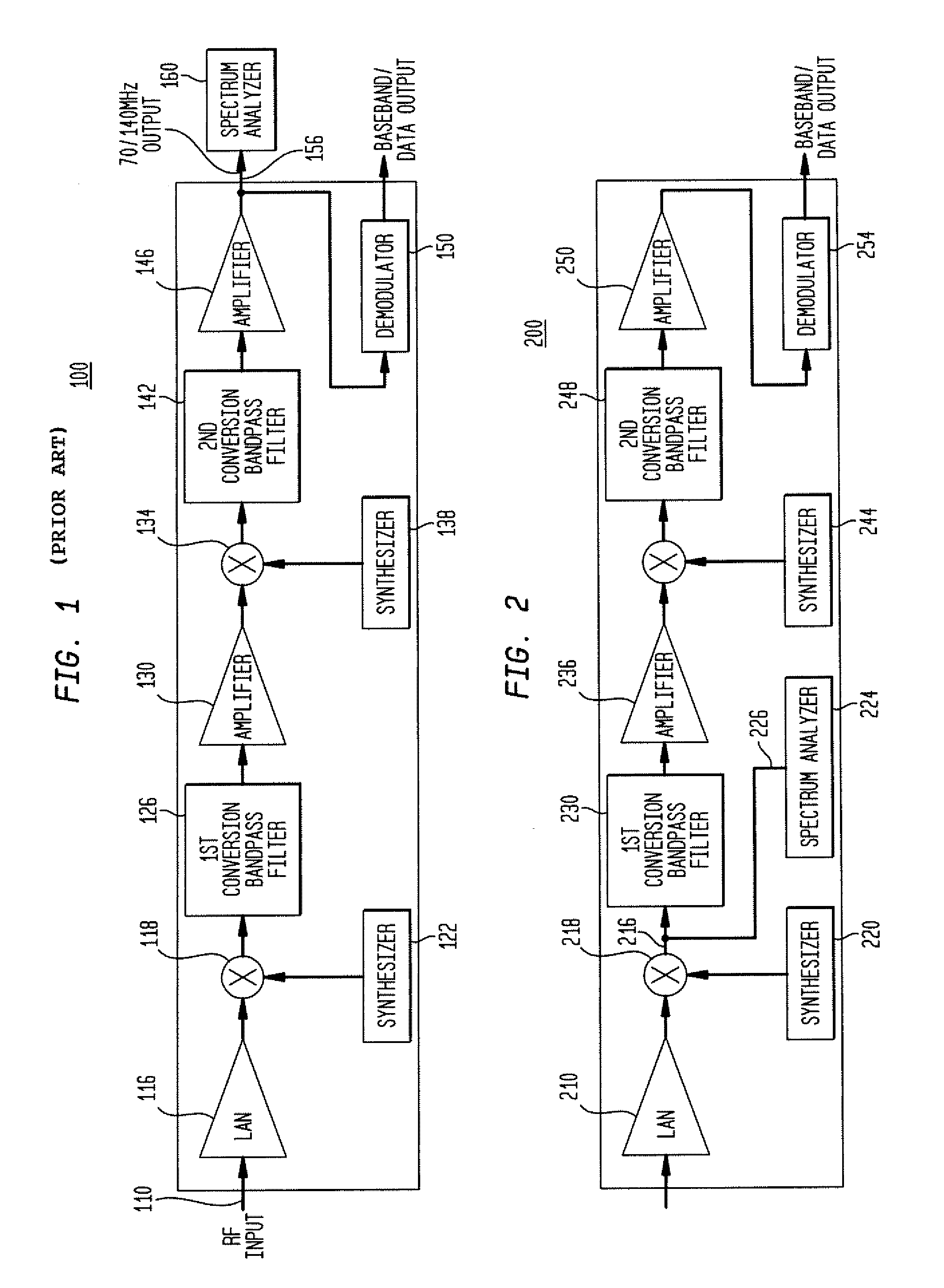
[0027]In accordance with an aspect of the present invention, a spectrum analyzer is integrated into the architecture of broadcast receiver. Such a receiver is adapted to receive ENG broadcast signals. In accordance with this aspect of the present invention, a more cost effective way for performing antenna alignment and perform spectrum analysis of the broadcast channel is provided. This aspect of the present invention advantageously does not require duplication of a receiver's amplifier and synthesizer circuitry. Functionally, this aspect of the present invention generally comprises placing a spectrum analyzer (SA) just after the first conversion circuit but prior to the first band pass filter. Note, however, that the signal may also be detected after the first band pass filter. FIG. 2 shows such a receiver 200 in accordance with an aspect of the present invention. As shown, the receiver 200 includes a first amplifier 210, which amplifies an RF signal received from a transmitter (no...


PUM


Abstract

A receiver for receiving a broadcast channel comprising a spectrum analyzer physically integrated into the receiver and operative to receive an intermediate frequency signal and process the spectral contents of the receive signal.

Description

CROSS-REFERENCE TO RELATED APPLICATIONS[0001]This application is a divisional of U.S. application Ser. No. 11 / 508,632, filed on Aug. 23, 2006, which claims the benefit of the filing date of U.S. Provisional Patent Application No. 60 / 710,833, filed Aug. 24, 2005, the disclosure of which is hereby incorporated herein by reference.BACKGROUND OF THE INVENTION[0002]The frequency band that the broadcasters use for electronic news gathering (ENG) is transitioning from 17 MHz bandwidth channels to 12 MHz bandwidth channels. To maintain a substantially consistent level of quality, the current analog FM modulation scheme will be changed to a digital modulation scheme. The current workflow for establishing and maintaining a link between antennas typically requires aligning a simplex link using verbal feedback from the receive site back to the transmitter site. The feedback is usually provided by having an operator at a transmit site make a voice connection using 2-way radio or cell phone. The ...

Claims


Application Information

Patent Timeline
IPC IPC(8): H04B1/06
CPCH04B1/28H04H20/04H04H40/27
Inventor PAYNE, IV, JOHN B.
Owner NUCOMM
Why Eureka
Try Eureka