
Polarimetric Selectivity Method for Suppressing Cross-Track Clutter in Sounding Radars

Active Publication Date: 2008-11-20
THE JOHN HOPKINS UNIV SCHOOL OF MEDICINE
View PDF22 Cites 6 Cited by
  • Summary
  • Abstract
  • Description
  • Claims
  • Application Information

AI Technical Summary

Benefits of technology

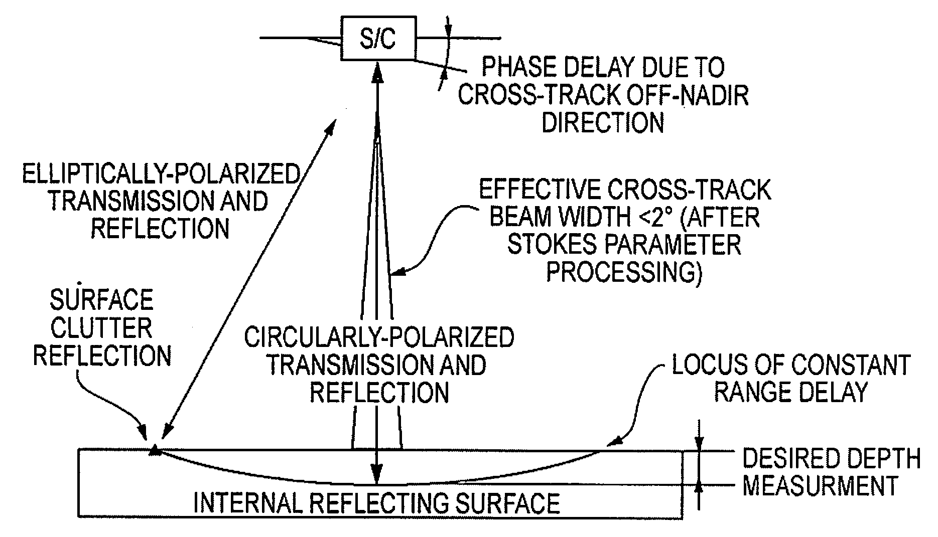
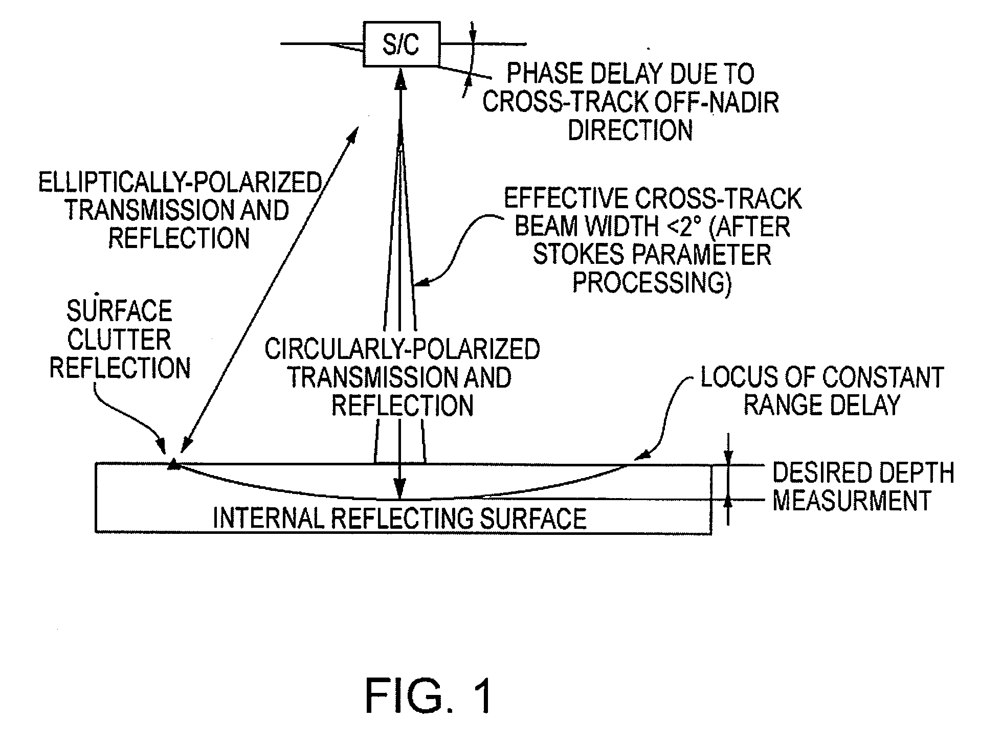
[0014]The invention comprises two polarimetric methods either of which can significantly reduce the cross-track clutter level relative to the desired sounding signals from depth. Both inventive methods take advantage of a hybrid-polarity method and archi

Problems solved by technology

These desired reflections (signals) are relatively weak, and may be obscured by the off-nadir returns.
However, the clutter that arises from off-nadir

Method used


Image

  • Polarimetric Selectivity Method for Suppressing Cross-Track Clutter in Sounding Radars
  • Polarimetric Selectivity Method for Suppressing Cross-Track Clutter in Sounding Radars

Examples


Example

[0020]In the following discussion, numerous specific details are set forth to provide a thorough understanding of the present invention. However, those skilled in the art will appreciate that the present invention may be practiced without such specific details. In other instances, well-known elements have been illustrated in schematic or block diagram form in order not to obscure the present invention in unnecessary detail.

[0021]The hybrid-polarity method and architecture summarized below is discussed more fully in U.S. patent application Ser. No. 12 / 116,357, filed May 7, 2008 which is incorporated herein by reference in its entirety.

[0022]Given that the transmitted polarization is circular, it would be natural to assume that the radar must be circularly polarized on receive. However, if the radar is coherently dual-polarized, then one form of its fundamental data product is the set of four Stokes parameters. The value of these parameters does not depend on the polarimetric basis in...


PUM


Abstract

Methods for suppressing cross-track clutter in a sounding radar utilize polarimetric selectivity in two ways: (1) transmitting full-beam circular polarization and separating the desired signal of interest from the clutter based on the signal and clutter having different polarizations, and (2) transmitting and receiving circular polarization at the radar's nadir and elliptical polarization at the radar's off-nadir regions and filtering out the elliptical polarization.

Description

CROSS-REFERENCE TO RELATED APPLICATIONS[0001]This application claims the benefit of prior filed, co-pending U.S. provisional application No. 60 / 938,226, filed on May 16, 2007, which is incorporated herein by reference in its entirety.STATE OF GOVERNMENTAL INTEREST [0002]This invention was made with Government support under National Aeronautics and Space Administration grant no. NNG05GL65G. The Government has certain rights in the invention.BACKGROUND OF THE INVENTION[0003]1. Field of the Invention[0004]The present invention relates generally to sounding radars and, more particularly, to methods for suppressing cross-track clutter by distinguishing between “signal” and “clutter” based on differences in their polarimetric signatures.[0005]2. Description of the Related Art[0006]Sounding by a down-looking radar from a large stand-off range, as from a high-altitude aircraft or an orbiting spacecraft measures reflectivity as a function of penetration into a medium such as ice sheets or dr...

Claims


Application Information

Patent Timeline
IPC IPC(8): G01S13/00
CPCG01S7/026G01S2013/9076G01S13/882G01S13/9076
Inventor RANEY, RUSSELL K.
Owner THE JOHN HOPKINS UNIV SCHOOL OF MEDICINE
Learn More