
Engine Start Device

Inactive Publication Date: 2008-11-20
HUSQVARNA ZENOAH
View PDF18 Cites 8 Cited by
  • Summary
  • Abstract
  • Description
  • Claims
  • Application Information

AI Technical Summary

Benefits of technology

[0027]Therefore, in accordance with the present invention, in normal, the engine is started by pulling the recoil rope at a stroke in the state of the first start mode. However, in the place in which the pulling operation of the recoil rope is hard to be executed, the engine is started by switching the first start mode to the second start mode firstly, pulling the recoil rope beforehand in the place in which the pulling operation is easily executed so as to accumulate the necessary accumulated force in the damping and accumulating means, thereafter switching the mode from the second start mode to the first start mode by using the mode switch operating means, for example, a one-push changing switch or the like in the working field so as to start the engine in a moment of time. The switch mode after the engine is started is always the first start mode, that is, the state in which the first and second engaging and disengaging means are detached from the damping and accumulating means and the driven section. In this first start mode, it is possible to obtain the same function as the machine type in which the spring force accumulated in the damping and accumulating means is naturally discharged and is not maintained after interrupting the pulling operation of the recoil rope, for example, the engine start device disclosed in the patent document 4 mentioned above. In this case, even if the pulling operation of the recoil rope is interrupted so as to leave before the engine is started, the accumulated force is naturally discharged from the damping and accumulating means so as to disappear. Accordingly, it is possible to prevent the engine from being accidentally started.
[0029]Since the time difference is provided in the disengagement of the engagement between the first engaging and disengaging member and the second engaging and disengaging member as mentioned above, only the engagement of the second engaging which engages with the driven section is first disengaged in the state in which the first engaging and disengaging member is engaged with the damping and accumulating means, thereby preventing the reverse rotation of the damping and accumulating means caused by the accumulated force of the damping and accumulating means so as to avoid a dispersion of the accumulated force, and transmitting the releasing force of the accumulated force transmitted from the damping and accumulating means to the crank shaft of the engine via the driven section at the same time so as to start the engine at a stroke. The engagement of the first engaging and disengaging member with the damping and accumulating means is disengaged at the same time when or just after the engine is started. As a result, almost all of the accumulated force accumulated in the damping and accumulating means is efficiently transmitted to the driven section, and it is possible to guarantee a secure engine start.
[0031]Further, in the case that the torque limit mechanism is further provided in the rotation portion of the engine start device mentioned above, it is possible to detect the fact that the accumulated force by the damping and accumulating means gets over the load necessary for starting the engine, thereby preventing the further accumulation. Accordingly, if the torque limit mechanism is operated, it is unnecessary to accumulate the force in the damping and accumulating means anymore. It is possible to pull the recoil rope in just proportion, and thus the unnecessary pulling operation is not required. In order to easily know the fact that the torque limit mechanism is operated, the signal generating means is operated together with the operation of the torque limit mechanism at a time when the necessary accumulated force is accumulated in the damping and accumulating means, thereby generating an informing signal, for example, a sound or a light.

Problems solved by technology

However, in this kind of engine start device, not only it is necessary to forcefully pull the recoil rope in a state of making a pulling speed of the recoil rope higher to some degree, but also a pulling length is long.
Accordingly, in many cases, an aged person and a weak person can not easily start the engine.
Further, in accordance with the start device, since the desired spring force can not be accumulated until plural times of pulling operations of the recoil rope are executed, it takes a lot of trouble for the operator having the normal force to start, and the operator can not be ever used to the operation.
However, for example, in the case that it is intended to execute a pruning of a tree by using a chain saw mounting the engine start device therein, most of the working field is necessarily high and has an unstable scaffold, and the other branches and leaves protrude around the working field.
Accordingly, it is unavoidable that the work would be done in the severe and narrow space where a large pulling operation of the recoil rope is hard to be executed.
At this time, in many cases, the pulling operation of the recoil rope can not be well executed by being obstructed by the branches and leaves therearound or preventing the scaffold from being fixed.
This operation not only be extremely hard to be executed but also require an extremely great pulling force, in comparison with the case of pulling the recoil rope to the near side.
There tends to be generated a situation that the accumulated force is released by some chance and the engine is accidentally started by the releasing fore.
Accordingly, it is impossible to optionally select the start timing of the engine even in this device.
In the case that this pulling operation is impossible, it is necessary to execute a manual work that leas to an extremely inefficient work.
However, the start is not achieved by the spring force, or there is a risk that the engine is started early.
On the other hand, the patent documents 3 to 5 can not forecast the timing at which the sufficient accumulated force for starting the engine is accumulated in the power spring.
Accordingly, the spring force of the power spring is changed in a long-term use, a deviation tends to be generated in the start timing of the engine, and it is impossible to forecast the deviation.
Thus, in many cases, a fear is generated at a time of starting.
However, it is hard to forecast the start timing in the same manner as the patent documents 2 to 5 mentioned above, and it is impossible to previously execute the pulling operation of the recoil rope so as to start the engine on the basis of a simple operation at an optional timing in an optional place.

Method used


Image

  • Engine Start Device
  • Engine Start Device
  • Engine Start Device

Examples


Embodiment Construction

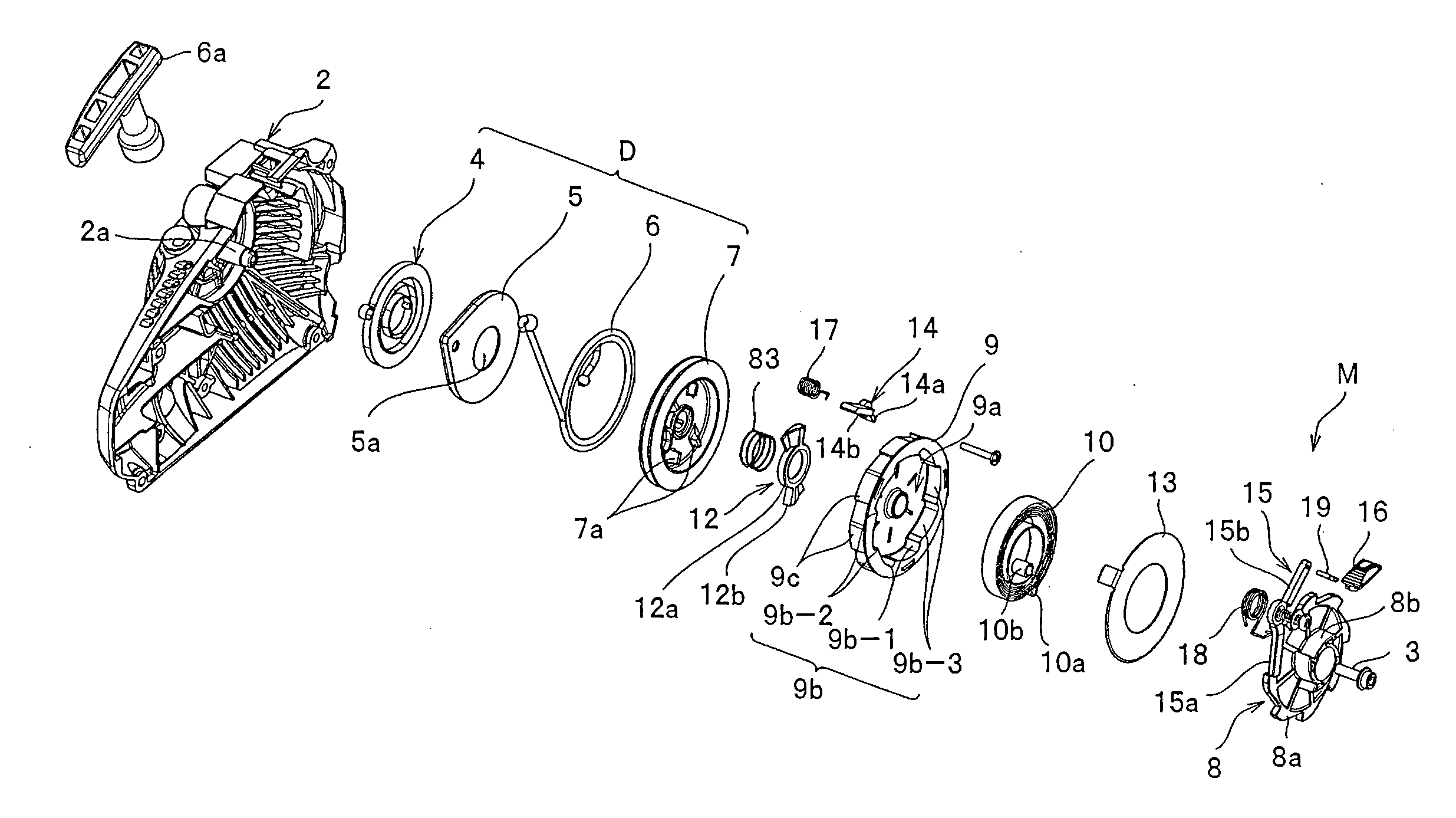
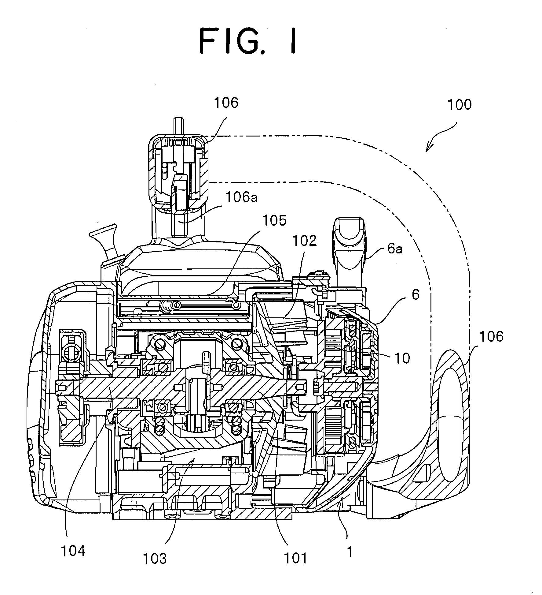
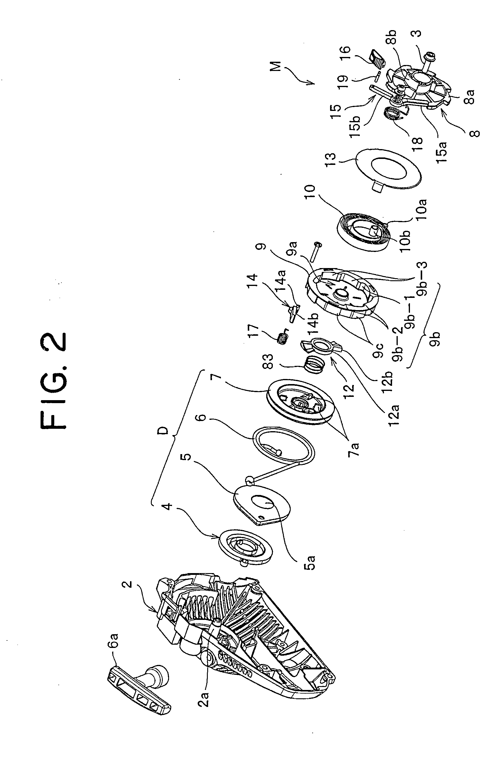
[0040]A description will be specifically given below of an embodiment of an engine start device of the present invention with reference to the accompanying drawings. In this case, in the present embodiment, there is exemplified a start device of a compact air-cooled internal combustion engine applied to a chain saw. However, the same kind of engine start device can be applied to a lawn mower, a rotary saw or the like.

[0041]FIG. 1 is a cross sectional view showing one embodiment of an internal structure of a compact engine mounting the engine start device of the invention therein. FIG. 2 is an exploded perspective view of constituting members arranged in an inner portion of a cover case of the engine start device. FIG. 4 is an internal structure view showing a detaching state of mode switching means in the start device. FIG. 5 is an internal structure view showing an engaging state of start timing selecting means.

[0042]A compact engine 100 according to the present embodiment is provi...


PUM


Abstract

An engine start device having a first start mode in which the engine is started on a spot by executing a start operation of the engine, and a second start mode in which a necessary accumulated force is previously accumulated in to start in one time in an optional place at an optional timing. In the first start mode, an accumulated force, accumulated by a rotation of a rotation drive section allows the engine to be started on the spot. If switched to the second start mode, the rotation of the rotation drive section is exclusively accumulated and released in the optional place at a desired time so as to start the engine in accordance with a one-touch operation.

Description

CROSS REFERENCE TO RELATED APPLICATIONS[0001]This is a U.S. national phase application under 35 U.S.C. § 371 of International Patent Application No. PCT / JP2005 / 023375 filed Dec. 20, 2005. The International Application was published in Japanese on Jun. 28, 2007 as International Publication No. WO 2007 / 072550 A1 under PCT Article 21(2), the content of which is incorporated herein in its entirety.TECHNICAL FIELD[0002]The present invention relates to a start device for an internal combustion engine, and more particularly to a compact engine start device which can smoothly start via damping and accumulating means such as an accumulating spring in accordance with a pulling operation of a recoil rope, in which the engine start device can make the pulling operation of the recoil rope unnecessary in a place where the pulling operation of the recoil rope is hard, can safely and securely start the engine in optional timing and place, and can prevent the engine from being carelessly started.BAC...

Claims


Application Information

Patent Timeline
IPC IPC(8): F02N3/02F02N5/02
CPCF02N3/02Y10T74/138F02N5/02
Inventor SUGISHITA, YUUNAKAJIMA, KAZUO
Owner HUSQVARNA ZENOAH
Learn More