Root apex position detection method
a detection method and apex technology, applied in the field of root apex position detection apparatus, can solve the problems of over distance contain an error, measured value contains an error, dentist may damage the root apex,
- Summary
- Abstract
- Description
- Claims
- Application Information
AI Technical Summary
Problems solved by technology
Method used
Image

Examples
first embodiment
[0024]the present invention will be described below with reference to the views of the accompanying drawing.
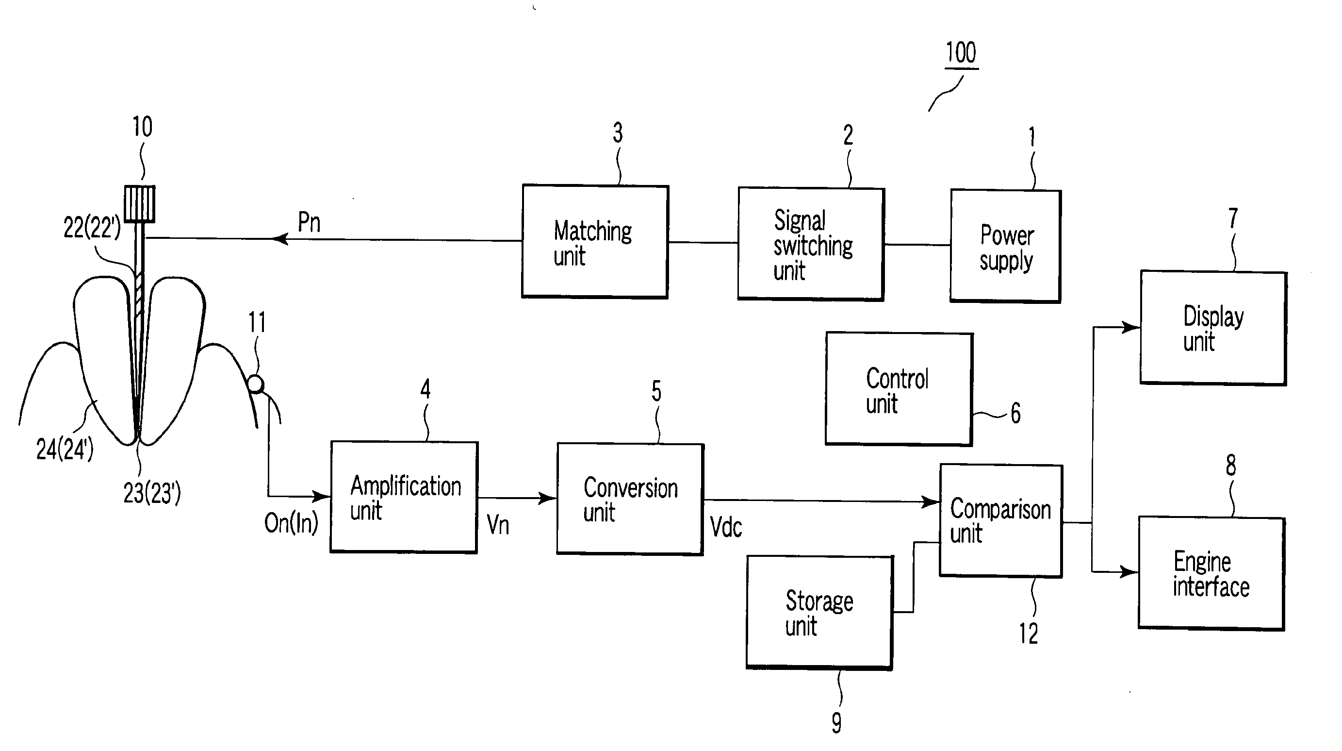
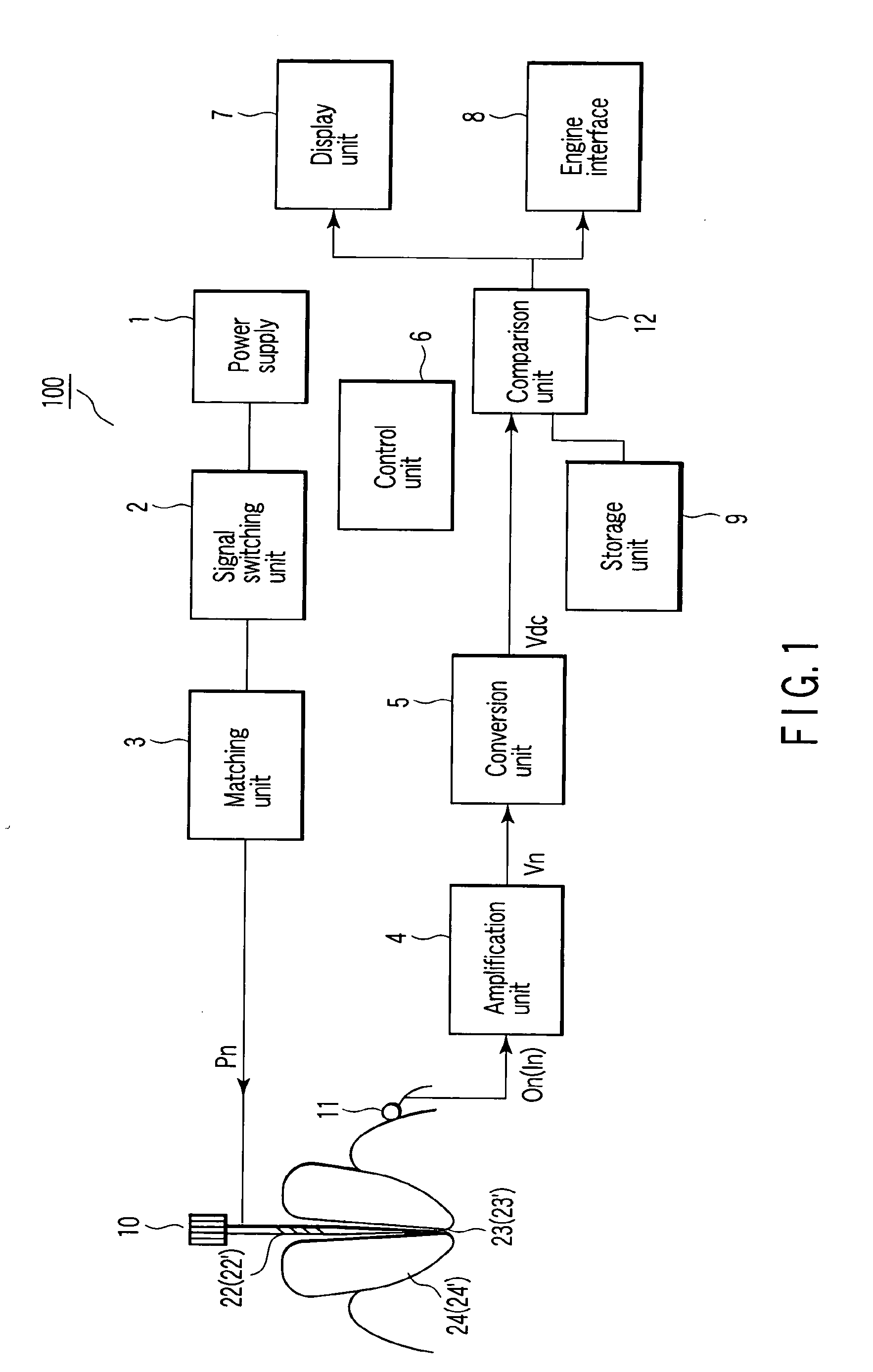
[0025]Referring to FIG. 1, a power supply 1 outputs a plurality of types of measurement signals Pn. The measurement signals Pn can be signals of two different frequencies of, e.g., 500 Hz and 2 kHz. The measurement signals Pn can be signals of three or more types of frequencies. The measurement signals Pn can be signals which differ from each other in at least one of frequency, waveform, or peak value. According to the invention of the present application, it is necessary to detect a plurality of types of electrical characteristic values between a measurement electrode 10 and a mouth electrode 11 on the basis of a plurality of types of measurement signals Pn, and the types of the signals can be selected on the basis of the principle of the invention of the present application to be described below.
[0026]In addition, although the measurement signals Pn are applied to the measur...
second embodiment
[0072]By improving the second embodiment, a state wherein the distal end of the measurement electrode 10 approaches the root apex position 23 can be detected more precisely. An example of this improvement is that an intra-root-canal-position-specific model data at least a point between point a1 and point a2 spaced apart by 1 mm is calculated by using an intra-root-canal-position-specific model data at the point a1 and an intra-root-canal-position-specific model data at the point a2 which are stored in the storage unit 9. By using this calculated approximate data as the above intra-root-canal-position-specific model data, the position of the distal end of the measurement electrode 10 can be detected more accurately.
[0073]The third embodiment will be described. As shown in FIG. 4, the third embodiment uses three types of data. Referring to FIG. 4, the data indicated on the ordinate are quantified values, the data marked with the crosses represent the values of measured data with a mea...
fifth embodiment
[0104]By generating the intra-root-canal-position-specific model data of the model tooth 24′ at 1-mm intervals from the root apex position, the fifth embodiment can detect in a resolution of 1 mm how the distal end of the measurement electrode 10 approaches the root apex position 23′.
[0105]The third function will be described next. The third function is to more precisely detect how the distal end of the measurement electrode 10 approaches the root apex position 23. The third function detects and displays that the distal end of the measurement electrode is located at least one position anywhere between positional in the root canal 22′ of the model tooth 24′ and position a2 ahead of the point a1.
[0106]The third function can use an electrical characteristic value change pattern of a test tooth. FIGS. 8 and 9 show examples of electrical characteristic value change patterns of a test tooth. For a model tooth 24′ whose root canal 22′ has an inverted conical shape, FIG. 8 shows the change ...
PUM
 Abstract
Description
Claims
Application Information
 - R&D
- Intellectual Property
- Life Sciences
- Materials
- Tech Scout
- Unparalleled Data Quality
- Higher Quality Content
- 60% Fewer Hallucinations
Browse by: Latest US Patents, China's latest patents, Technical Efficacy Thesaurus, Application Domain, Technology Topic, Popular Technical Reports.
© 2025 PatSnap. All rights reserved.Legal|Privacy policy|Modern Slavery Act Transparency Statement|Sitemap|About US| Contact US: help@patsnap.com