
Pedal device with function of adjusting pedal effort and hysteresis

Active Publication Date: 2008-11-13
DONG HEE IND
View PDF9 Cites 28 Cited by
  • Summary
  • Abstract
  • Description
  • Claims
  • Application Information

AI Technical Summary

Benefits of technology

[0011]Accordingly, the present invention is made to solve the above-mentioned problems, an object of the present invention is to provide an electronic type pedal device detecting a level of stepping by pressing a pedal to generate an electrical signal, which can alleviate fatigue of a driver's ankle due to a frequent acceleration operation by differently setting a level of reaction force that is applied to the driver at the time of stepping and releasing a pedal by adjusting a pre-compression force to a return spring disposed at the pivot end of a pedal arm and adjusting a friction force at a pivot end of the pedal arm, satisfying a user's preference by appropriately adjusting the reaction force.

Problems solved by technology

However, in the acceleration pedal devices as described above in the related art, according to the mechanical acceleration pedal device, a hysteresis, when a reaction force applied to the driver pressing the pedal is smaller than a reaction force applied to the driver releasing the pedal due to the friction between a wire and a tube in the cable at the same time the pedal is being pressed and released, is caused.
However, this has minimal effect on tuning the pedal effort.
Therefore, the electronic acceleration pedal device that generates the same magnitude of reacting force while pressing and releasing the pedal in the related art, increases the fatigue of the driver's ankle as the driver repeatedly presses and releases the pedal.
As a result, this deteriorates the response of the pedal.
Further, since the reacting force depends on the natural elasticity of the return spring in the electronic acceleration pedal device in the related art, it is difficult to freely perform the tuning of pedal effort according to the driver's preference.

Method used


Image

  • Pedal device with function of adjusting pedal effort and hysteresis
  • Pedal device with function of adjusting pedal effort and hysteresis
  • Pedal device with function of adjusting pedal effort and hysteresis

Examples


Embodiment Construction

[0021]Hereinafter, a detailed description of embodiments of the present invention will be given with reference to the accompanying drawings.

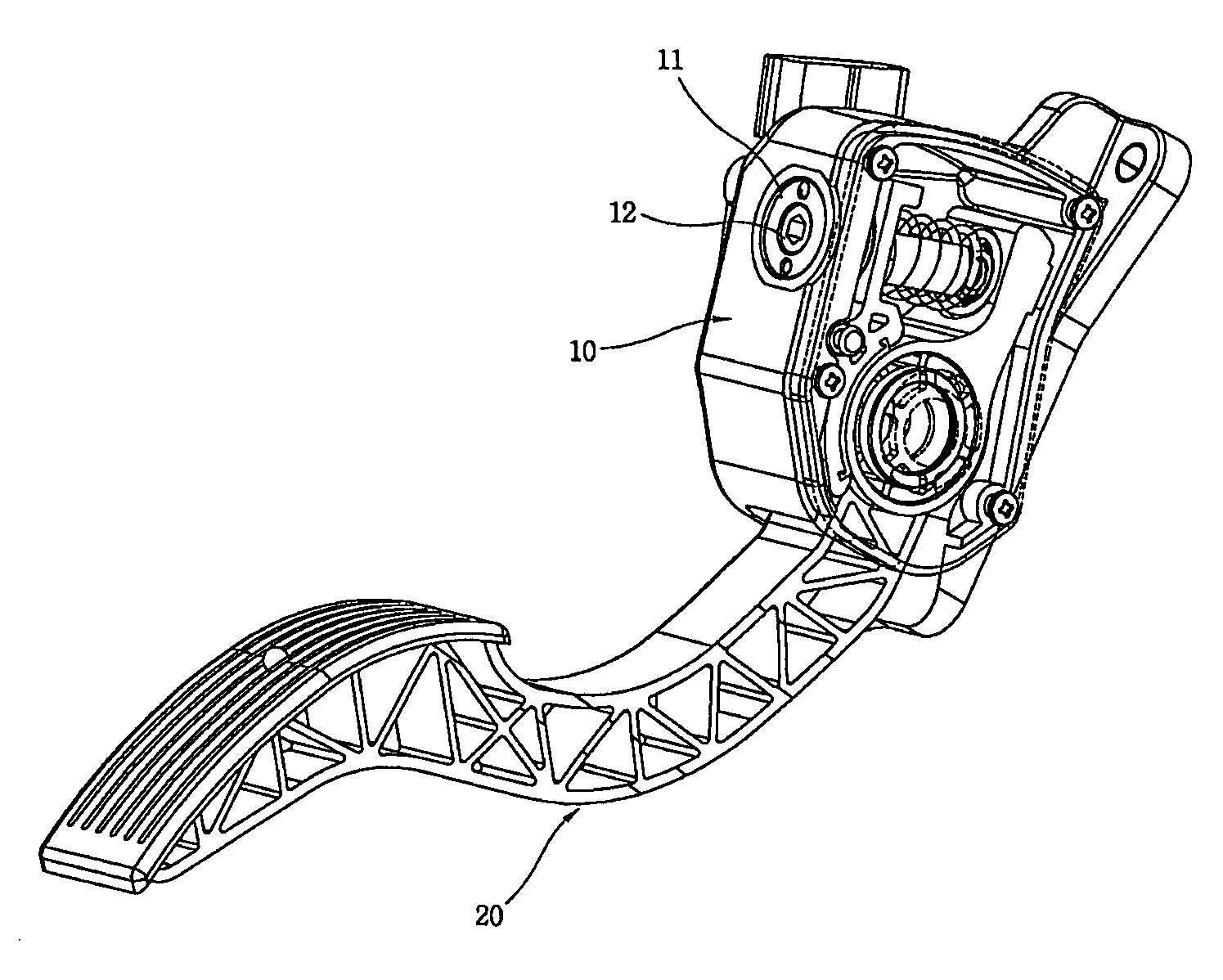
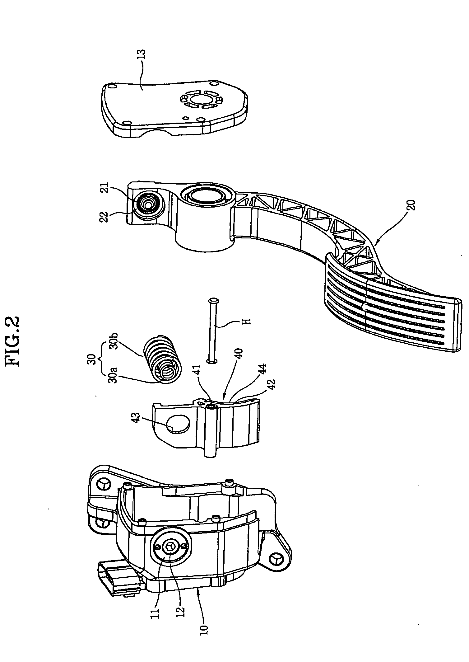
[0022]As shown in FIG. 1, an electronic pedal device according to an embodiment of the invention includes a housing 10 that is fixed to a car body, a pedal arm 20 that is hinged to the housing 10 and pivots about the housing 10, and an elastic member that is disposed between the housing 10 and the pivot end of the pedal arm 20 and provides a return force to the pedal arm 20.

[0023]Further, the electronic pedal device according to an embodiment of the invention further includes a pedal effort adjusting unit and a hysteresis adjusting unit. The pedal effort adjusting unit is disposed at the housing 10 and presses an end of the elastic member to adjust a pre-compression force to the elastic member, thereby adjusting a pedal effort to the pedal arm 20. The hysteresis adjusting unit is movably disposed at the housing 10 to press the hinged portion of ...


PUM


Abstract

An object of the present invention is to provide a pedal device which can alleviate fatigue of a driver's ankle due to a frequent acceleration by differently setting the amount of reaction force applied when the driver presses and releases a pedal, by adjusting pre-compression force against a return spring disposed at a hinged portion of a pedal arm and adjusting a friction force on a hinged portion of the pedal arm, and satisfying a user's preference by properly adjusting the reaction force. In order to accomplish the above-mentioned object, the invention provides a pedal device with a function of adjusting a pedal effort and hysteresis that includes: a housing fixed to a car body; an arm hinged to the housing; an elastic member disposed between the housing and the pivot end of the pedal arm, and providing a return force to the pedal arm; a pedal effort adjusting unit disposed in the housing and pressing an end of the elastic member to adjust a pre-compression force to the elastic member force; and a hysteresis adjusting unit movably disposed in the housing to press the hinged portion of the pedal arm and adjusting the amount of change in stroke-to-pedal effort while the pedal arm operates.

Description

CROSS-REFERENCE TO PRIORITY APPLICATION[0001]The benefit of priority is claimed to Republic of Korea patent application number 10-2007-0045875, filed May 11, 2007, which is hereby incorporated by reference in its entirety.BACKGROUND[0002]1. Field of the Invention[0003]The present invention relates to a pedal device of a vehicle, more particularly, to an electronic pedal device detecting a level of stepping by pressing a pedal to generate an electrical signal, which can promote a change of characteristics of a pedal effort and hysteresis adapted to a driver's propensity by adjusting an elastic force of a return spring disposed at the pivot end of a pedal arm and providing a returning force, and a friction force at a hinged portion of the pedal arm.[0004]2. Description of the Related Art[0005]In general, a vehicle traveling is accelerated when the driver presses the pedal device and the pedal device is frequently pressed by the driver while the vehicle is traveling; therefore, researc...

Claims


Application Information

Patent Timeline
IPC IPC(8): G05G1/30
CPCY10T74/20534G05G1/38B60K26/02
Inventor KIM, TAEHOKIM, DONGHWAN
Owner DONG HEE IND
Learn More