
Method and system for vibration avoidance for automated machinery

Active Publication Date: 2008-11-06
TEKNIC
View PDF17 Cites 3 Cited by
  • Summary
  • Abstract
  • Description
  • Claims
  • Application Information

AI Technical Summary

Benefits of technology

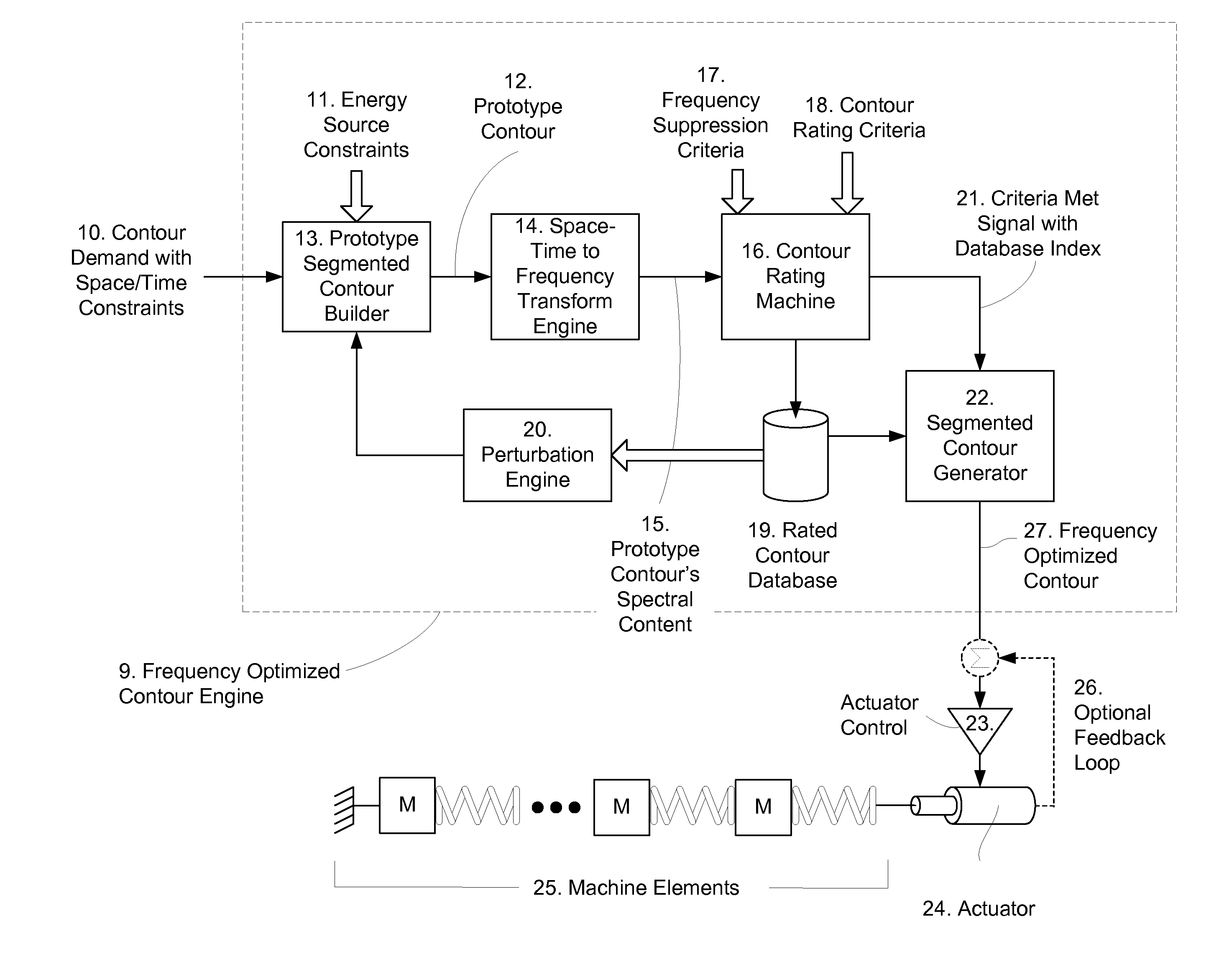
[0013]We have developed a machine control system that produces these frequency-optimized-contours when given the goals the space-time contours must attain (typically points in space and time) and constraints on the frequency content of the resulting space-time contour. Limits can be imposed based not only on the energy level at the exciting frequencies but the energy limit can be extended to a band about these frequencies. Using frequency bands as limits makes the technique robust should the exciting frequencies shift in the machine due to manufacturing tolerance, wear, aging, drift, etc. of the machine elements. This band (or these bands) of frequencies are defined herein as frequencies of interest which, along with their suppression criteria are specified by frequency-elimination criteria. No expressions that quantify the dynamics of the machine elements are required for this invention to operate properly, freeing the designer from tedious analysis.
[0014]Frequency-optimized-contours are produced, without any post filtering or shaping, by concatenating multiple space-time contour segments together in such a way as to be mostly free of energy at the frequencies of interest while meeting the other design goals specified for the space-time contour. The segments used to construct these frequency-optimized-contours are a series of concatenated polynomial segments as further discussed below. When these frequency-optimized-contours are fed as a command to machine controller through an actuator or actuators, the energy at the frequencies of interest is low enough to avoid deleterious vibration from occurring while still meeting the machine performance objectives.

Problems solved by technology

Automated machines often have performance limitations caused by the vibration within the mechanisms and the stationary structure to which these mechanisms are attached within the machinery.
Often, no matter how much energy is applied to a mechanism it is unable to perform the assigned task faster than a certain rate because vibrations interfere with the successful completion of the task.
In these machines, although the application of more energy typically allows the mechanism to operate faster, the increased energy causes the amplitude of the vibrations to increase.
The increased vibrations interfere with the machine's operation, especially the timely and precise stopping of an apparatus at a target point or value.
These methods can only solve the problem to a limited degree, tend to increase the assembled cost of the machine, and require additional design effort and engineering cost to implement.
Sometimes the successful application of these mechanical solutions is not possible because of constraints imposed by the very task the machine is attempting to perform.
If the drumstick strikes a foam pad on a board the result is a dull thud because the pad is similar to well damped machine elements without resonance so no frequencies are amplified or sustained.
If the drumstick strikes a gong or a tuning fork the result is sustained vibration.
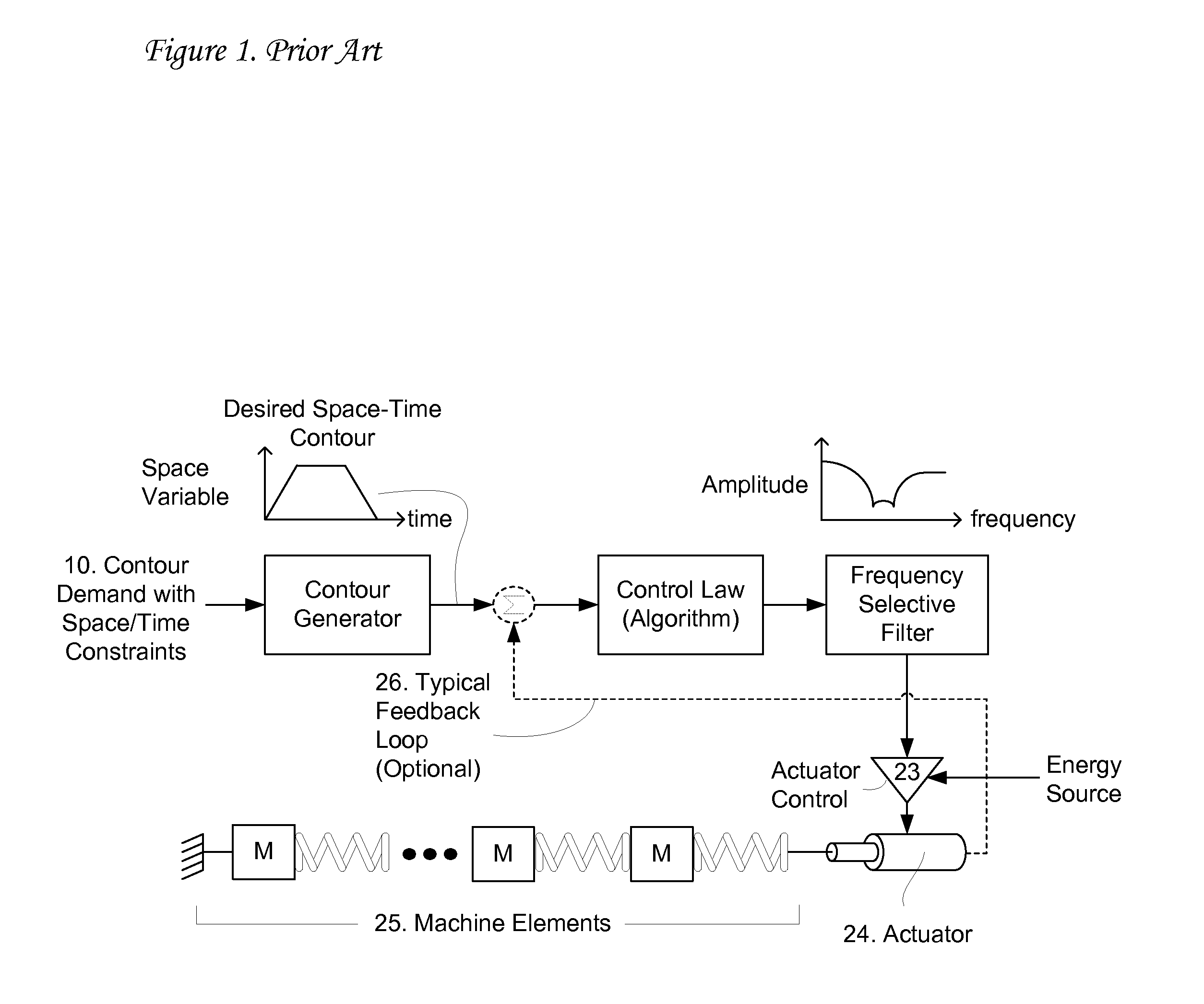
This control method has limitations in that the space-time contour command itself still likely has energy at frequencies that will cause vibration in the machine.
By removing the exciting frequencies from the energy source driving the machine elements, errors are induced limiting the faithful following of the space-time contour, and often, these errors are unacceptable to the machine operation.
In many instances, if the filtering of the energy source is not sufficient and / or robust, the feedback control, attempting to follow the desired space-time contour will force energy back into the system at the exciting frequencies, limiting the usefulness of this control solution.
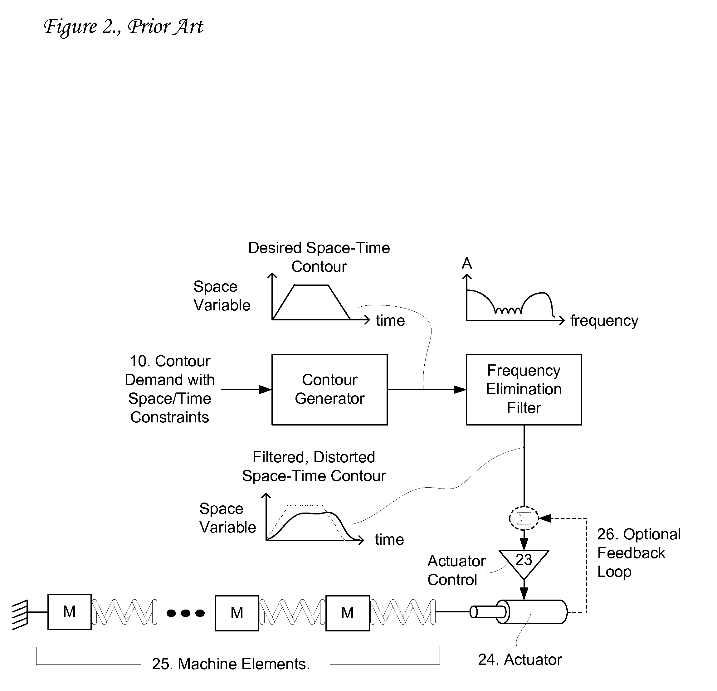
The unfortunate side effect of this technique is distortion of the “non-exciting” contour from the original desired space-time contour.
Space-time contour filtering produces, in any case, a contour that is distorted from the original designed space-time contour such that it usually degrades the performance of the machine, often causing it to not meet the design objectives.
In the case of a space-time contour that is intended to move a mechanical load from one point to another and then stop, this method always increases the time between these points because delay, inherent in the filter operation, necessarily lengthens the “non-exciting” contour.
This has the likely effect of slowing the overall machine, reducing its operating throughput.

Method used


Image

  • Method and system for vibration avoidance for automated machinery
  • Method and system for vibration avoidance for automated machinery
  • Method and system for vibration avoidance for automated machinery

Examples


Embodiment Construction

[0023]As previously noted, frequency-optimized-contours are produced in our invention, without any post filtering or shaping, by concatenating multiple space-time contour segments together in such a way as to be mostly free of energy at the frequencies of interest while meeting the other design goals specified for the space-time contour. The segments used to construct these frequency-optimized-contours are a series of concatenated polynomial segments where each polynomial segment can be defined by the equation: x=k0+k1t+k2t2+ . . . +kntn, etc. or equivalent algebraic forms, the independent variable t being time. These segments can define the variable to be controlled (e.g. speed or distance) versus time, or define one of the controlled variable's time-derivatives (e.g., the slope of the speed vs. time, etc.).

[0024]As an example, if the frequency-optimized-contour to be designed was to be a distance vs. time contour, the concatenated segments used to construct the contour could be li...


PUM


Abstract

A method for vibration avoidance in automated machinery produces actuator space-time contours that meet design objectives of the machinery while suppressing energy content at frequencies in the space-time contour, by concatenating multiple space-time contour segments together in such a way as to be mostly free of energy at the frequencies of interest while meeting other specified design goals. The segments used to construct these frequency-optimized-contours are a series of concatenated polynomial segments, the independent variable t being time. These segments can define the variable to be controlled (e.g. speed or distance) versus time, or define one of the controlled variable's time-derivatives (e.g., the slope of the speed vs. time, etc.). When these frequency-optimized-contours are fed as a command to a machine controller through an actuator or actuators, the energy at the frequencies of interest is low enough to avoid deleterious vibration from occurring while still meeting the machine performance objectives.

Description

BACKGROUND OF THE INVENTION[0001]1. Field of the Invention[0002]The invention pertains generally to the field of methods for minimizing unwanted system dynamics. More particularly, the invention pertains to a method and system for vibration avoidance for use with automated machinery.[0003]2. Description of Related Art[0004]Automated machines often have performance limitations caused by the vibration within the mechanisms and the stationary structure to which these mechanisms are attached within the machinery. Often, no matter how much energy is applied to a mechanism it is unable to perform the assigned task faster than a certain rate because vibrations interfere with the successful completion of the task. In these machines, although the application of more energy typically allows the mechanism to operate faster, the increased energy causes the amplitude of the vibrations to increase. The increased vibrations interfere with the machine's operation, especially the timely and precise ...

Claims


Application Information

Patent Timeline
IPC IPC(8): G05B13/02G06F17/30
CPCG05B19/404G05B2219/41117G05B2219/49054
Inventor TESTA, FRANCIS JOSEPH
Owner TEKNIC
Learn More