
Lever operated pivoting float with generator

a technology of lever operated pivoting float and generator, which is applied in the direction of electric generator control, machines/engines, mechanical equipment, etc., can solve the problems of failure or utilization of devices

Inactive Publication Date: 2008-11-06
OLSON ENTERPRISES INC
View PDF58 Cites 37 Cited by
  • Summary
  • Abstract
  • Description
  • Claims
  • Application Information

AI Technical Summary

Benefits of technology

[0007]The disclosure also teaches a spring configuration adapted for use with the lever arm and with the generator. The disclosure also teaches a sha

Problems solved by technology

However these devices have not been successful or utilized.

Method used


Image

  • Lever operated pivoting float with generator
  • Lever operated pivoting float with generator
  • Lever operated pivoting float with generator

Examples


Embodiment Construction

[0022]While this invention is susceptible of embodiments in many different forms, there is shown in the drawings and will herein be described in detail embodiments of the invention with the understanding that the present disclosure is to be considered as an exemplification of the principles of the invention and these examples are not intended to limit the broad aspect of the invention. The above general description and the following detailed description are merely illustrative of the subject invention and additional modes, advantages and particulars of this invention will be readily suggested to those skilled in the art without departing from the spirit and scope of the invention.

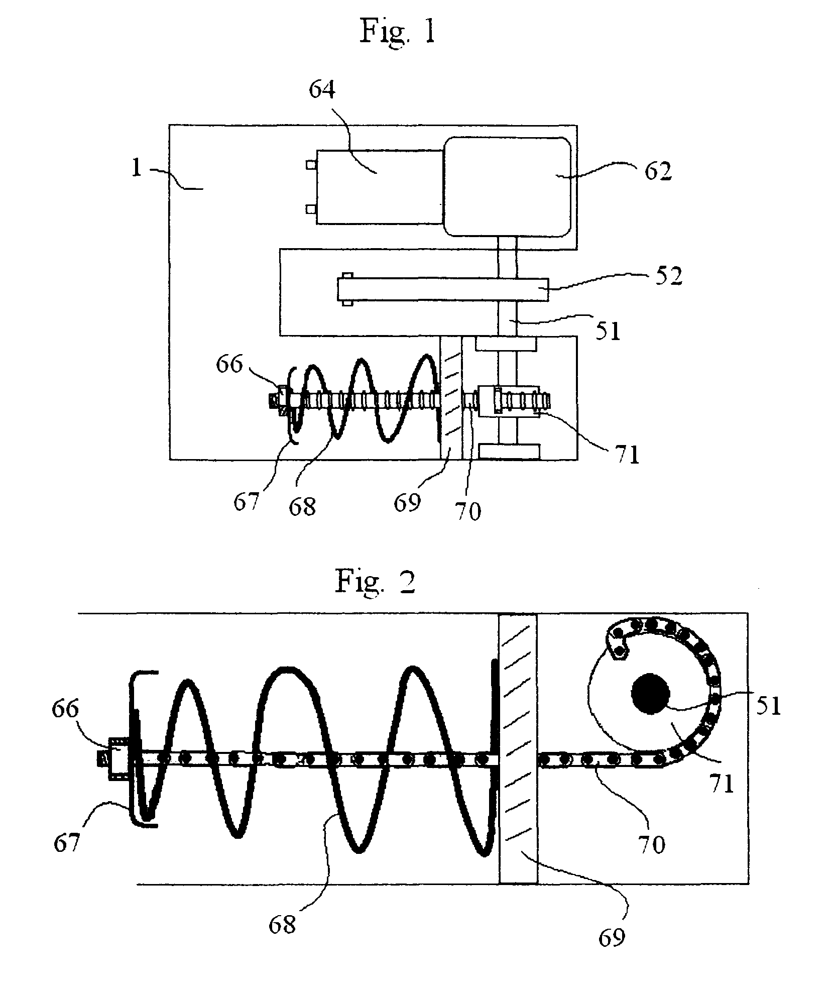
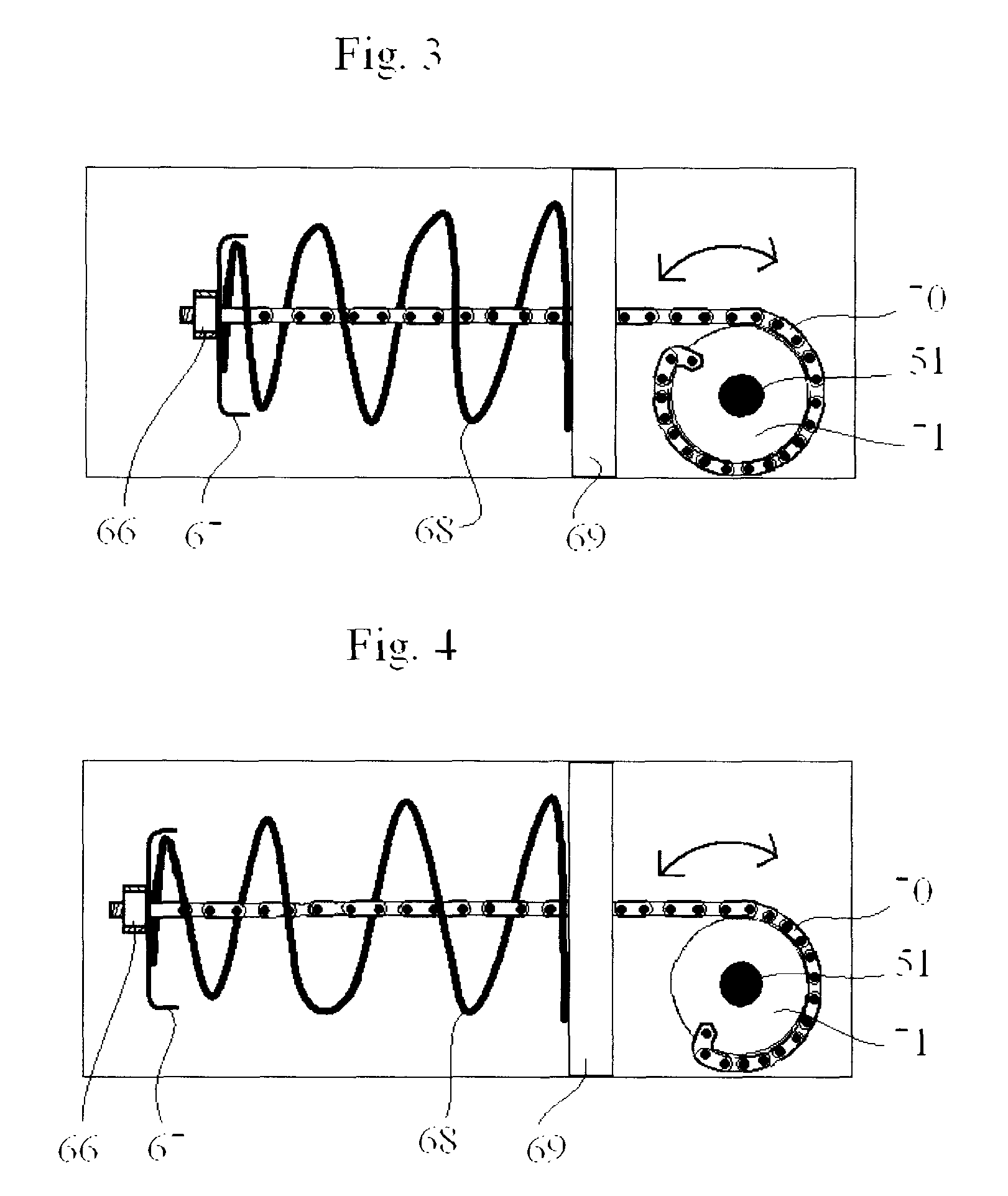
[0023]The disclosure pertains to improvement in the return spring used in the lever operated pivoting float with generator. For example, see FIG. 2. As part of the operational cycle, the lever arm is pulled down as a result of ocean waves lifting the float and a torsion spring returns the lever to the uprig...


PUM


Abstract

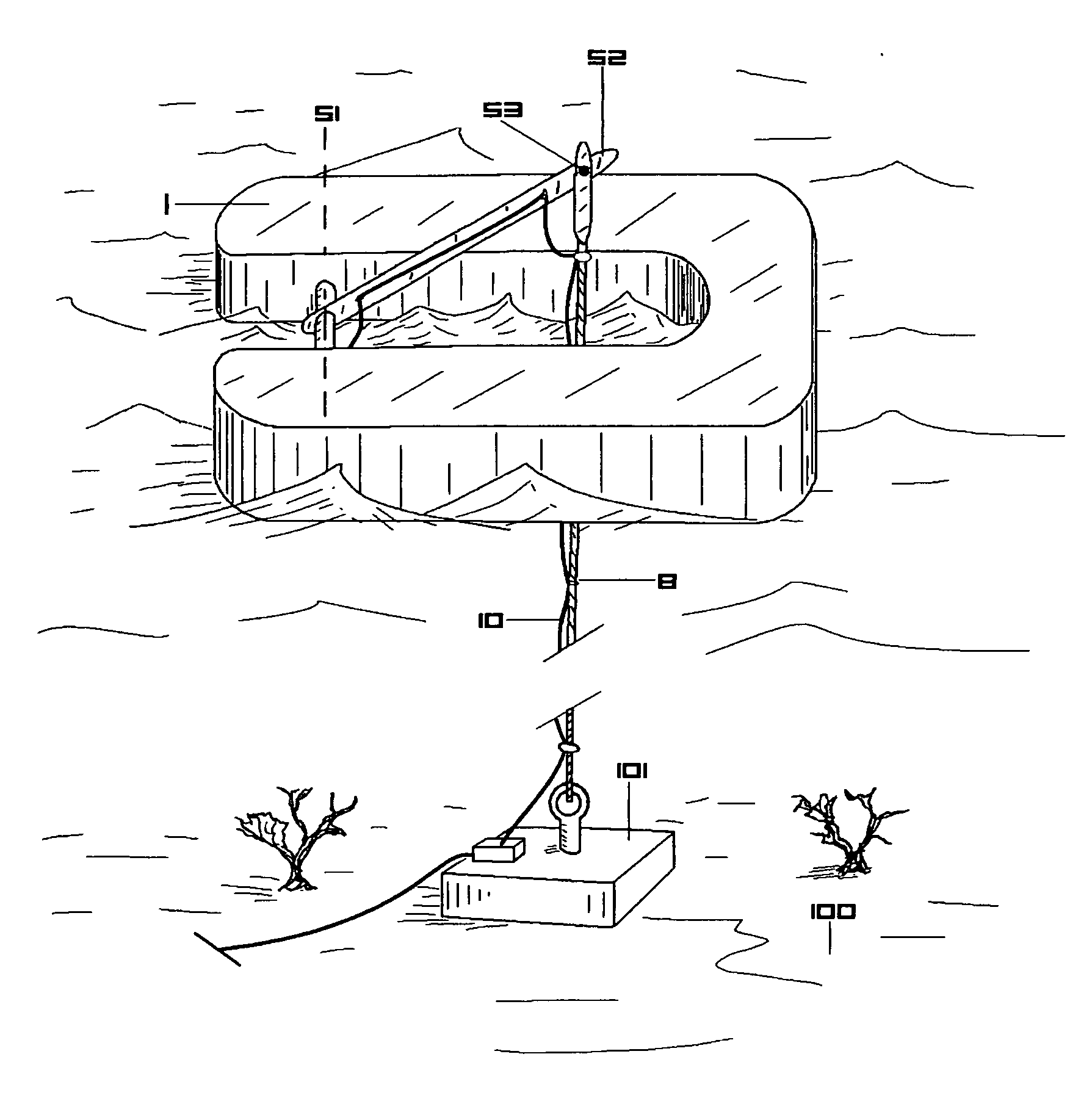
The disclosure teaches improvements of the lever operated pivoting float with generator. The improved parts include an improvement in the torsion spring system, more streamlined floatation, counter weighted and ballast balanced, buoyant lever arm and a shock absorbing lever arm. The device can also be use up side down. The disclosure also teaches a floating electric power generator including a buoyant float component, a lever arm pivoting on a shaft of the float and attached to a submerged structure, and an electrical generator that includes a shaft that turns in response to the pivoting of the lever arm. Also disclosed is a floating electric power generator including a float in a “U” or horseshoe shape with an opening for mounting the pivoting lever arm on a shaft, a generator contained within one arm of the float, a combination spring and shaft component wherein the springs are compressed by pulling down of the pivoting lever arm, and energy from the compression or relaxation of the power is communicated to the generator shaft to power the generator. The disclosure teaches a floating electric power generator comprising: a float in a “U” or horseshoe shape with an opening for mounting a pod shaped pivoting lever arm on a shaft, a generator contained within the lever arm pod, a chain, coil spring and end cap configuration in communication with a shaft within the lever arm wherein the chain is wrapped about the shaft when the lever arm is pulled down and thereby compressing the spring, a gear component on the shaft in communication with at least one other gear fixed to the generator rotating shaft so that as the lever arm rotates about the shaft, the generator rotating shaft is turned. The pod holds the weight of the generator and the generator acts as a counter weight and ballast to force the back end of the float under as it is lifted out of the water. The pivoting floatation device has large ends and thinner mid sections so that the float will enter the water smoothly.

Description

RELATED APPLICATIONS[0001]This application claims the benefit of and priority to provisional application No. 60 / 994,213 entitled “Float Device for Lever Operated Pivoting Float with Generator” filed Sep. 18, 2007 and which is incorporated by reference herein. This application also claims the benefit of and priority to provisional application No. 61 / 123,484, entitled “Improved Torsion Spring System for Lever Operated Pivoting Float with Generator” filed Apr. 9, 2008, and which is incorporated by reference herein. This application also claims the benefit of and priority to provisional application No. 61 / 072,678 entitled “Improved Torsion Spring System for Lever Operated Pivoting Float with Generator” filed Apr. 2, 2008, and which is incorporated by reference herein. The application also claims the benefit of and priority to provisional application No. 61 / 003,247 entitled “Lever Arm and Generator Housing” filed Nov. 15, 2007, and No. 61 / 003,242 entitled “Energy Steady Release Device”, ...

Claims


Application Information

Patent Timeline
IPC IPC(8): F03B13/12
CPCF03B13/1815F05B2240/93Y02E10/38Y02E10/30
Inventor OLSON, CHRIS
Owner OLSON ENTERPRISES INC
Learn More