
Enhanced patient mobility system

a patient mobility and patient technology, applied in the field of enhanced patient mobility system, can solve the problems of patient standing, patient trip and fall, easy upset, etc., and achieve the effect of improving patient mobility system, low cost, and convenient cleaning

Inactive Publication Date: 2008-11-06
TURNER DAVID B +1
View PDF18 Cites 5 Cited by
  • Summary
  • Abstract
  • Description
  • Claims
  • Application Information

AI Technical Summary

Benefits of technology

[0002]The present invention is a Enhanced Patient Mobility System (EPMS) for use by ambulatory or recovering patients in and about the home, rehab, sub-acute, and hospital facilities. It provides such person with ease of mobility, stability and the ability to transport needed treatment apparatus and necessities.
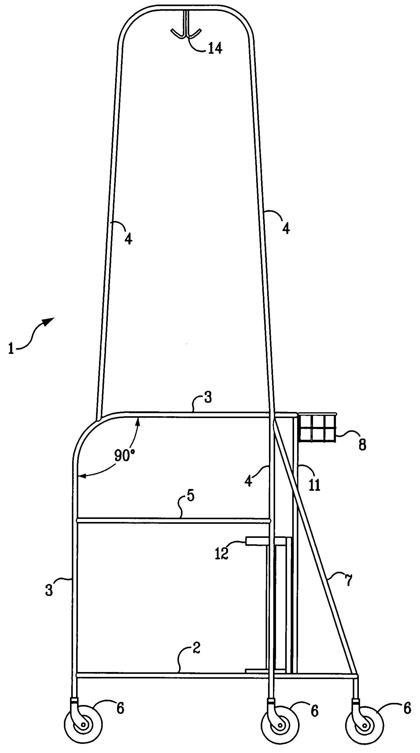
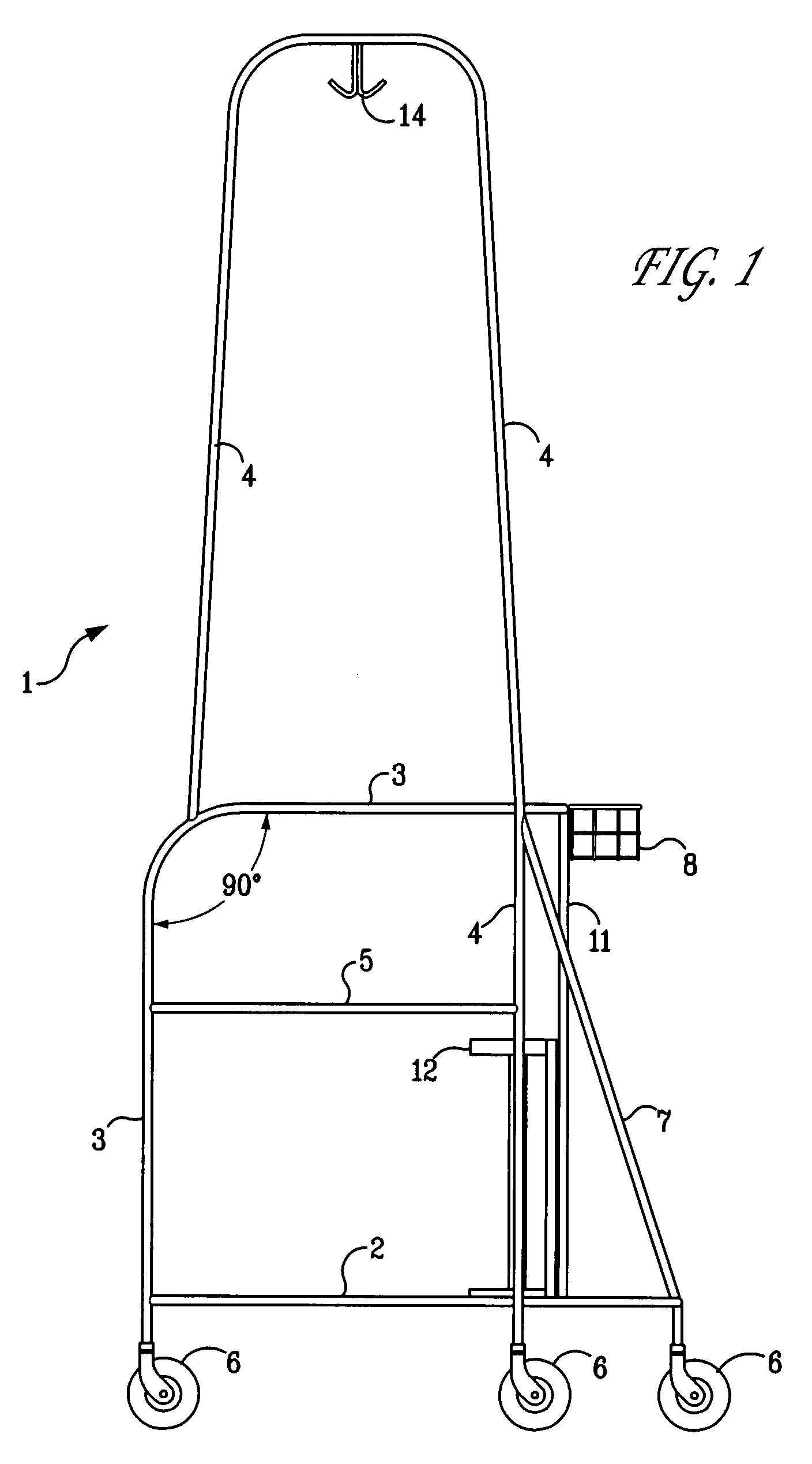
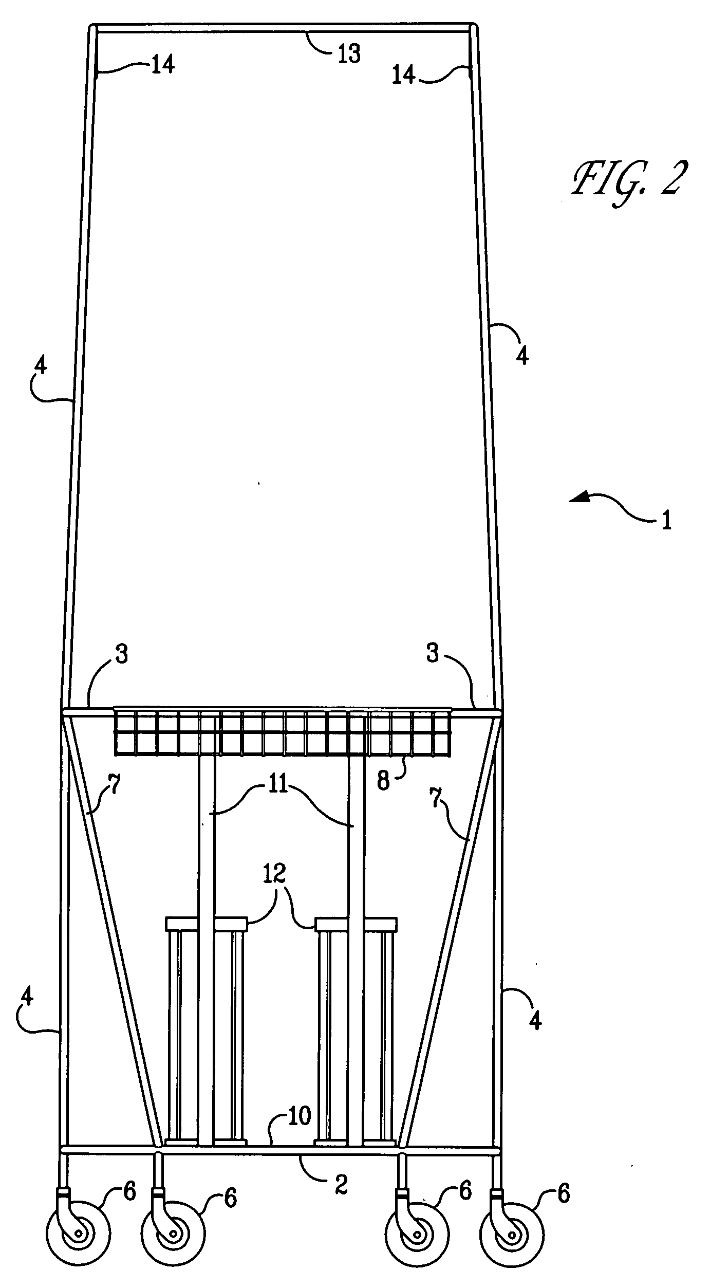
[0003]One object of the present invention is to provide a low cost, sturdy, tubular framework which is easily cleanable and easily maneuverable having sufficient carrying capacity to meet an ambulatory patient's needs. In this regard it is necessary for the EPMS to provide walking space for the patient which is approachable from the rear of the EPMS with the EPMS being wide enough to establish a stable, secure base member. It is a function of the present invention to provide parallel bars for supporting apparatus in the form of two cross bar members, at or above knee level. It is also an object of the present invention to provide a stable difficult to tip EPMS device having six conductive castor type wheels four of which are located forward of the patient's center of gravity to enable the patient to rest by leaning on the device and move easily forward even on different surfaces / terrain. It is a further object of the invention to provide support means at a level above the patients head to accommodate intravenous equipment such as medical drips and the like. It is a further object of the invention that the user be able to use the device in association with a wheelchair and / or bed so that transference from the wheelchair to the device is safe and easy to accomplish with qualified personnel assisting.
[0004]Specifically the invention is a EPMS for use by ambulatory or recovering patients in and about home, rehab, sub-acute, and hospital facilities providing such person with ease of mobility, stability and the ability to transport needed treatment apparatus and necessities comprising: a low-cost, sturdy, tubular framework having a lower U-shaped base frame member, an upwardly extending midframe member and two identical side frame members standing in parallel planes each attached at its lower extremity to the lower U-shaped base frame member and at its midsection to the upward extending midframe member wherein the lower U-shaped base frame member includes a crossbar member interconnecting the two legs of the U-shaped base frame member at a distance from the terminal ends of the legs of the U-shaped member to provide walking space for the patient and wherein the two identical side frame members are also generally U-shaped with the bow of the U upwardly extending and the two downwardly extending legs of the U being attached to opposite sides of the midframe member and each side frame member having one leg of the U-shaped member extending beyond the midframe member and terminating in a castor type wheel, the lower U-shaped member further having four conductive castor type wheels, two of which are attached each to a separate distil end of the U-shaped base frame member and two of which are attached in spaced relationship from each other on the bow of the U-shaped base frame member, there being a total of six conductive castor type wheels lying in the same plane, the EPMS further comprising two support bars each extending from the midframe member to a separate extended end of a separate side member at a point above the plane of the castor type wheels for facilitating the support of necessary medical devices and apparatus which must be transported by a ambulatory patient, and a ambulatory optional carrying basket attached to the extended midframe member at a point between and above the four forwardmost castor type wheels, the EPMS further comprising two rigid support bars attached to and extending from the U-shaped base frame member at a point above the point of attachment of the two forwardmost castor type wheels in spaced relationship to each other upwardly at an incline and attached to the midframe member at the forwardmost point of attachment of the U-shaped side frame members, the EPMS further comprising two parallel upstanding single bar supports running from the crossbar of the lower base frame member and attached to the forwardmost portion of the upwardly extending midframe member and being provided each with a gas cylinder holder for holding oxygen and like needed gases, the side frame members being attached to each other by a crossbar attached and extending therebetween at the highest point of the side frame members which is not higher than about 6.25 feet above the plane of the conductive castor type wheels.

Problems solved by technology

Many times it is a problem to provide ambulatory patients with a way for them to move about.
The most frequent means of providing ambulatory assistance to a patient is the use of a patient stand; however, patient stands commonly have a relatively narrow base and are easily upset if the wheels encounter an obstruction or irregularity in the surface upon which they are traveling.
Because the stands are relatively unstable there is the danger of upsetting the stand and causing the patient to trip and fall.
Such accidents endanger the patient and others, not to mention the potential damage to equipment and interruption of treatment frequently necessary while patients are ambulatory.
Very typically such devices however are cumbersome and difficult to maneuver and provide little in the way of equipment and personal effects storage and mobility.

Method used


Image

  • Enhanced patient mobility system
  • Enhanced patient mobility system
  • Enhanced patient mobility system

Examples


Embodiment Construction

[0009]The present invention is a EPMS 1 for use by ambulatory or recovering patients which is of simple design yet is durable, sturdy, mobile and easy to clean. There are three major components to the EPMS. The first is a lower U-shaped base frame member 2. The base frame member like the entire EPMS is preferably constructed of aluminum or light steel tubing. Preferably one-half (½) or (¾) inch aluminum conduit is used. The various parts are fabricated together by welding or other suitable attachment means including but not limited to nuts and bolts, screws, clamping fasteners, adhesives and the like, all of which are known to those skilled in the art. The lower U-shaped base frame member has rounded corners so as not to present sharp corners which could pose a safety hazard or could easily catch on adjacent items. The rounded corners can serve as a bumper means allowing the EPMS to easily glance off items inadvertently contacted while the EPMS is in use. The lower U-shaped base fra...


PUM


Abstract

The invention is an Enhanced Patient Mobility System for use by ambulatory or recovering patients. The Enhanced Mobility System is fabricated from sturdy tubular material and has a lower U-shaped base frame member mounted on casters with an upwardly extending mid frame member and two identical side frame members lying in parallel planes and each attached at it's lower extremity to the lower U-shaped base frame member. The U-shaped base frame member, the mid frame member and the two identical side frame members define a walking space for the patient with provision for the possibility of the patient also being able to move about with oxygen tanks, a patient intravenous drip apparatus and other medical devices and apparatus which must be transported by an ambulatory patient.

Description

BACKGROUND OF THE INVENTION[0001]The invention described herein is a Enhanced Patient Mobility System (EPMS) for use by ambulatory or recovering patients. Frequently it is important for hospital patients to be ambulatory as soon as possible to enable a shorter post operative recovery and hospital stay. Many times it is a problem to provide ambulatory patients with a way for them to move about. The most frequent means of providing ambulatory assistance to a patient is the use of a patient stand; however, patient stands commonly have a relatively narrow base and are easily upset if the wheels encounter an obstruction or irregularity in the surface upon which they are traveling. Because the stands are relatively unstable there is the danger of upsetting the stand and causing the patient to trip and fall. Such accidents endanger the patient and others, not to mention the potential damage to equipment and interruption of treatment frequently necessary while patients are ambulatory. Such ...

Claims


Application Information

Patent Timeline
IPC IPC(8): A61H3/04
CPCA61H3/04A61H2003/004
Inventor TURNER, DAVID B.MYERS, RALPH
Owner TURNER DAVID B
Learn More