
Shock proof structure for storage device of electronic device

a technology of electronic devices and storage devices, applied in the direction of recording information storage, record carrier contruction details, instruments, etc., can solve the problems of ineffective prevention of storage devices, inability to effectively prevent, and difficult to maintain vehicle stability while moving

Inactive Publication Date: 2008-11-06
PORTWELL
View PDF2 Cites 7 Cited by
  • Summary
  • Abstract
  • Description
  • Claims
  • Application Information

AI Technical Summary

Benefits of technology

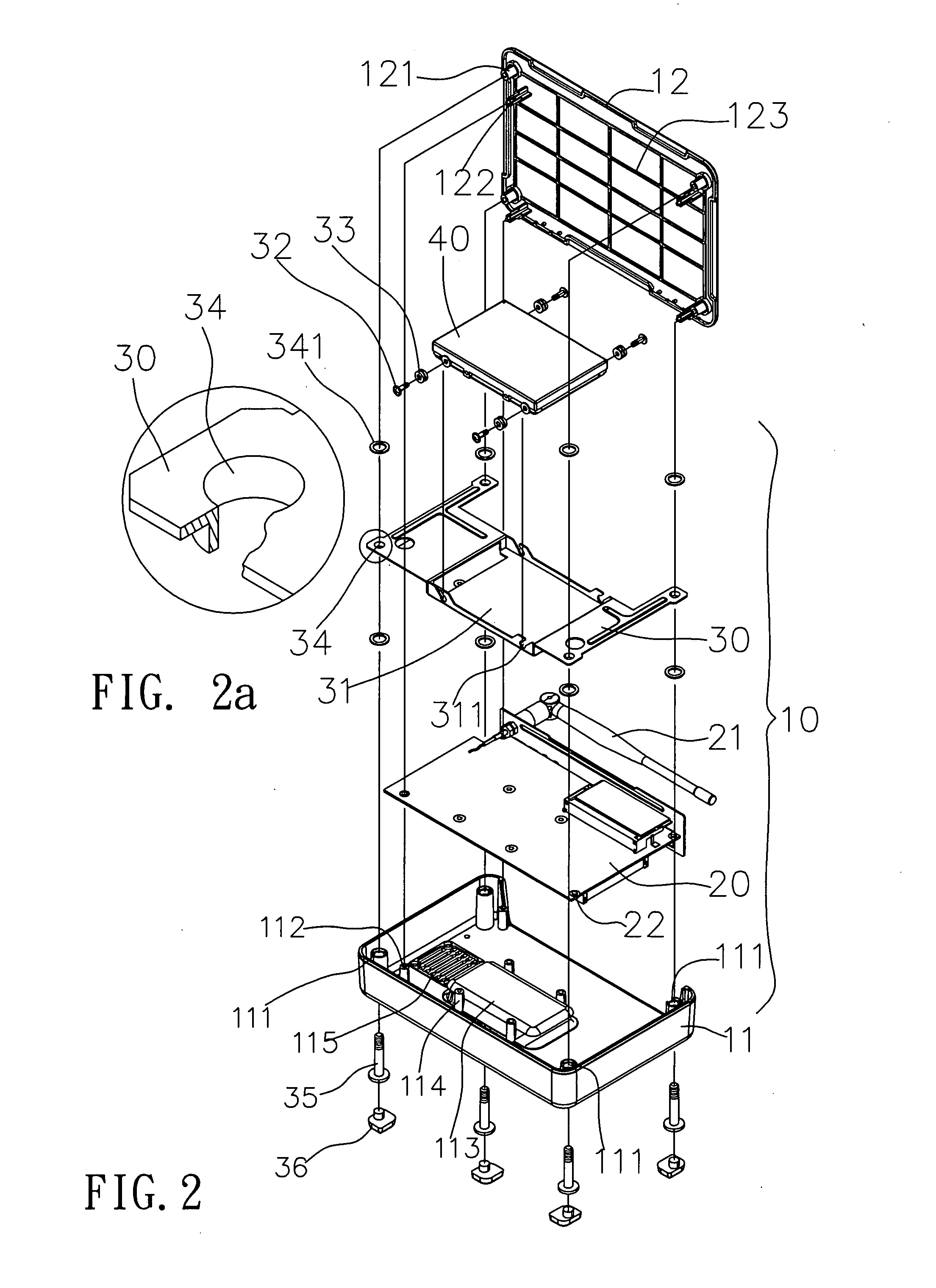
[0006]The primary objective of the present invention is aimed to provide a first buffer element installed between the shock proof rack for supporting the storage device and the storage device in order to minimize left / right swaying.
[0007]A secondary objective of the present invention is to provide a second buffer element installed between the housing and the shock proof rack to minimize shocks coming from the housing.

Problems solved by technology

However, due to different road conditions, a vehicle is difficult to maintain its stability while moving.
Swaying left and right and vibrating up and down are unavoidable.
Also, even for home computers, the storage device cannot effectively prevent shocks from earthquake or collision by merely using latching or fastening by screws.

Method used


Image

  • Shock proof structure for storage device of electronic device
  • Shock proof structure for storage device of electronic device
  • Shock proof structure for storage device of electronic device

Examples


Embodiment Construction

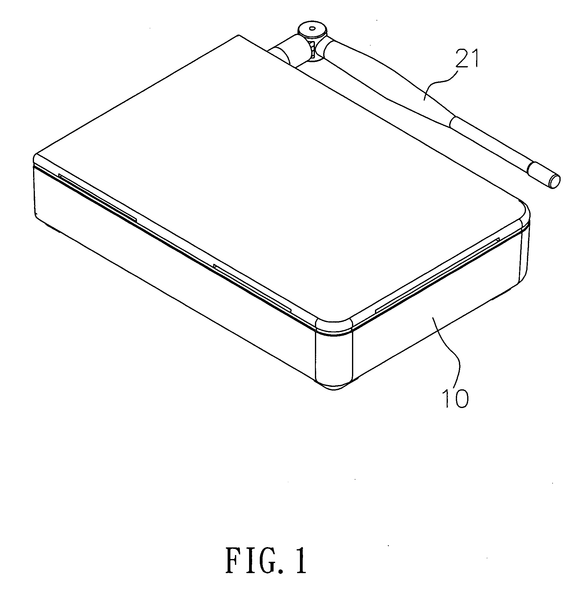
[0021]First, referring to FIGS. 1, 2, 2a, 3 and 4, the present invention relates to a shock proof structure for a storage device of an electronic device, whereby the structure has a housing 10 formed by a base structure 11 and an upper lid 12. There is a support pillar 111 on the edge of the base structure, and the support pillar 111 is hollow in the center, and the height of the support pillar 111 is lower than the height of the base structure 11, and on the lateral inside of the support pillar 111 are erected with hollow pillars 112, and a protruded platform 113 is set at a certain position of the base structure11. Corresponding support pillars 114 are set by the side of the platform 113, and next to the platform 113 is a heat dissipation hole 115. Further, there are protruded pillars 121 on the upper lid 12 corresponding to the support pillars 111 whereby the protruded pillars 121 can be precisely inserted into the support pillars 111, and by the lateral inner side of the protrud...


PUM


Abstract

The present invention discloses a shock proof structure for a storage device of an electronic device or more particularly to a shock proof structure being used on motor vehicles or in environments with strong vibration or shocks. The structure has a housing and inside the housing is a shock proof rack with an indented storage space for fixing the storage device. The first and second buffer elements are installed on the periphery and edges of the shock proof rack, so that the shock proof rack is suspended in the housing, thereby bringing about shock proof effect with the buffering action of the first and the second buffer elements.

Description

BACKGROUND OF THE INVENTION[0001]1. Field of the Invention[0002]The present invention relates to a shock proof structure for a storage device of an electronic device, and more particularly to suspend a storage device inside a housing to be cushioned and damped by a first buffer element and a second buffer element on the periphery and edges.[0003]2. Description of the Related Art[0004]Usually, the electronic devices (such as computer and DVD player, etc.) are placed in a stable environment. Hence, shock proof for the storage device of such electronic devices is often focused on minimizing shocks of the storage device with the buffer elements of a shock proof rack. However, the use of computer to control relevant operations of motor vehicles has become popular and would gradually replace conventional circuit control in the past. However, due to different road conditions, a vehicle is difficult to maintain its stability while moving. Swaying left and right and vibrating up and down are...

Claims


Application Information

Patent Timeline
Patent Type & Authority Applications(United States)
IPC IPC(8): A47F7/00
CPCG06F1/187G11B33/08G11B33/124
Inventor HUNG, TE-FU
Owner PORTWELL
Learn More