
Memory card storing case structure

a memory card and storage case technology, applied in the direction of packaging, container/bottle construction, other accessories, etc., can solve the problems of prior art not meeting user requirements in actual use and the structure easily falling apart, so as to increase the fastening stability, prevent the structure from falling apart, and avoid the effect of fractur

Inactive Publication Date: 2008-11-06
LEE YUN HSIU
View PDF9 Cites 7 Cited by
  • Summary
  • Abstract
  • Description
  • Claims
  • Application Information

AI Technical Summary

Benefits of technology

[0005]A primary objective of the present invention is to provide an improved structure of memory card storing case which uses a wavelike ear portion disposed at a front end of a frame portion of an upper cover to movably join with corresponding wavelike fastening portions disposed at two sides of a recess of a base, thereby increasing fastening stability, avoiding fracture and preventing the structure from breaking if dropped from a high place, thereby effectively protecting memory cards. Moreover, overall structure is light and small, thus providing effectiveness to save on material, space, and so on, and thereby increasing practicability and convenience of the overall structure.
[0006]Another objective of the present invention is to provide the improved structure of memory card storing case with an extended portion located at an outer side of a frame strip circum located on a periphery of the base to enable the upper cover to fixedly position on and cover the base and provide shockproof protection if dropped from a high place, thereby increasing practicability of the overall structure.
[0007]Yet another objective of the present inventions is to provide the improved structure of memory card storing case with an arcuate concave surface formed at a front end of the extended portion of the base, thereby substantially improving shockproof effectiveness, as well as effectively reducing impact force effect and preventing the structure from coming apart if dropped from a high place, and thus increasing practicability of the overall structure.
[0008]Yet another objective of the present inventions is to provide the improved memory card storing case structure with an extended surface formed at a front end of the upper cover, wherein the extended surface is larger than the arcuate concave surface at the front end of the base, thereby facilitating opening and increasing practicability of the overall structure.
[0009]In order to achieve the aforementioned objectives, the improved memory card storing case structure of the present invention comprises a base and an upper cover. A periphery of the base has a frame strip circum located thereon, and a recess is formed at a front end of the frame strip. Wavelike fastening portions are respectively formed on two sides of the recess, and a plurality of position fixing protruding ribs are located within the base to enable holding at least one memory card. A periphery of the upper cover is provided with a frame portion, and a wavelike ear portion located at a front end of the frame portion enables movable joining to the corresponding wavelike fastening portions on the two sides of the recess of the base. Accordingly, the present invention provides effectiveness of a structural configuration that enables a stable joining together of the upper cover and the base, convenience of storage, saving on costs, shockproof protection and convenience of opening, thereby increasing practicability and convenience of the overall structure.

Problems solved by technology

However, the structures of prior memory card storing case are provided with effectiveness to hold various types of memory card, but, because the clasp protruding pieces have a limited serviceable life, thus, fracture possibly occurs after fastening a number of times or the structure easily comes apart if dropped from a high place.
Hence, the prior art does not meet with user requirements in actual use.

Method used


Image

  • Memory card storing case structure
  • Memory card storing case structure
  • Memory card storing case structure

Examples


Embodiment Construction

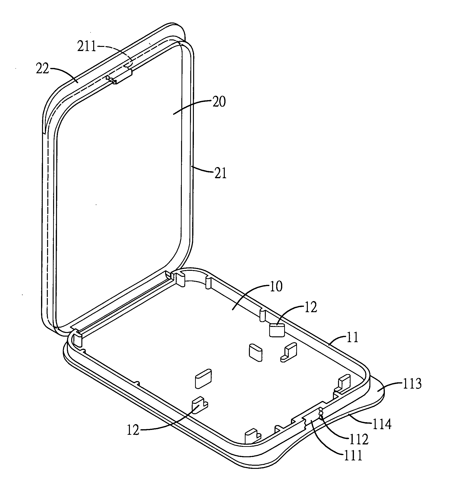
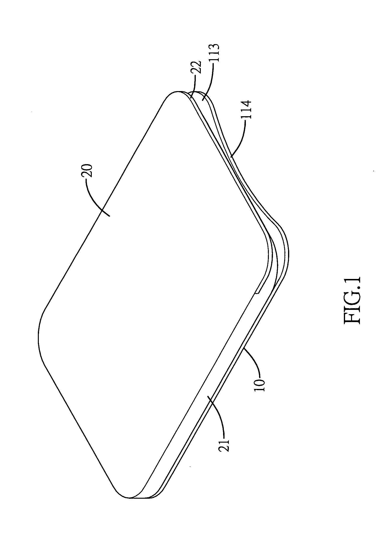
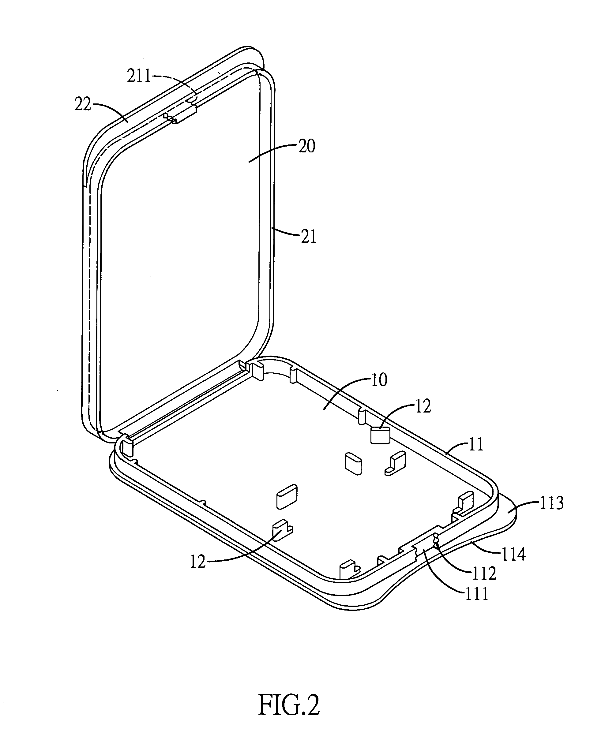
[0017]Referring to FIGS. 1 to 4, which show an improved structure of memory card storing case of the present invention, comprising:

[0018]A base 10, a periphery of which has a frame strip 11 circum located thereon, and a recess 111 is formed at a front end of the frame strip 11.

[0019]Wavelike fastening portions 112 are respectively formed on two sides of the recess 111, and a plurality of fixed protruding ribs 12 are located within the base 10 to enable holding at least one memory card 30 or card adapter device.

[0020]An upper cover 20, a periphery of which is provided with a frame portion 21; a wavelike ear portion 211 is located at a front end of the frame portion 21, and the wavelike ear portion 211 enables movable joining to the corresponding wavelike fastening portions 112 on the two sides of the recess 111 of the base 10. The base 10 and the upper cover 20 are formed as an integral configuration enabling mutual movable joining of the upper cover 20 to the base 10 (the base 10 an...


PUM

PropertyMeasurementUnit
thicknessaaaaaaaaaa
fastening stabilityaaaaaaaaaa
structureaaaaaaaaaa

Abstract

The present invention provides an improved structure of memory card storing case, which includes a base and an upper cover. A periphery of the base has a frame strip circum located thereon, and a recess is formed at a front end of the frame strip. Wavelike fastening portions are respectively formed on two sides of the recess, and a plurality of fixed protruding ribs are located within the base to enable holding at least one memory card or card adapter device. A periphery of the upper cover is provided with a frame portion, and a wavelike ear portion is located at a front end of the frame portion. The wavelike ear portion enables movable joining to the corresponding wavelike fastening portions on the two sides of the recess of the base. Accordingly, the present invention provides effectiveness of a structural configuration that enables a convenient storage and a shockproof protection.

Description

BACKGROUND OF THE INVENTION[0001](a) Field of the Invention[0002]The present invention relates to an improved structure of memory card storing case, and more particularly to a structural assembly of a base and an upper cover that enables mutual movable joining of the base and the upper cover, thereby providing effectiveness of a stable fastening, convenience of storage, saving on costs, shockproof protection and convenience of opening. Moreover, the present invention is suitable for various types of memory card storing cases or devices with similar structures.[0003](b) Description of the Prior Art[0004]Prior structures of memory card storing case primarily include a base and an upper cover pin configured thereto, wherein a fastening device between the base and the upper cover is used to fasten the two together. A base surface formed on the base is characterized in that a plurality of clasp protruding pieces are formed on and upwardly protrude from the base surface, and a support mou...

Claims


Application Information

Patent Timeline
Patent Type & Authority Applications(United States)
IPC IPC(8): B65D85/00
CPCB65D75/22B65D2585/86
Inventor LEE, YUN-HSIU
Owner LEE YUN HSIU
Learn More