
Method and system for solving an optimization problem with dynamic constraints

a dynamic constraint and optimization problem technology, applied in the field of methods and systems for solving dynamic constraints, can solve problems such as failure of genetic operators, and failure of genetic operators to solve optimal solutions for current constraints

Active Publication Date: 2008-10-30
21ST CENTURY TECH
View PDF96 Cites 42 Cited by
  • Summary
  • Abstract
  • Description
  • Claims
  • Application Information

AI Technical Summary

Benefits of technology

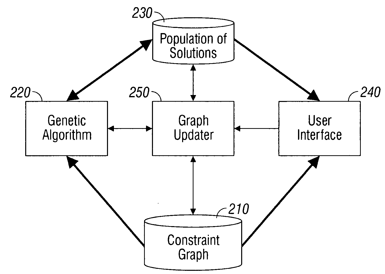
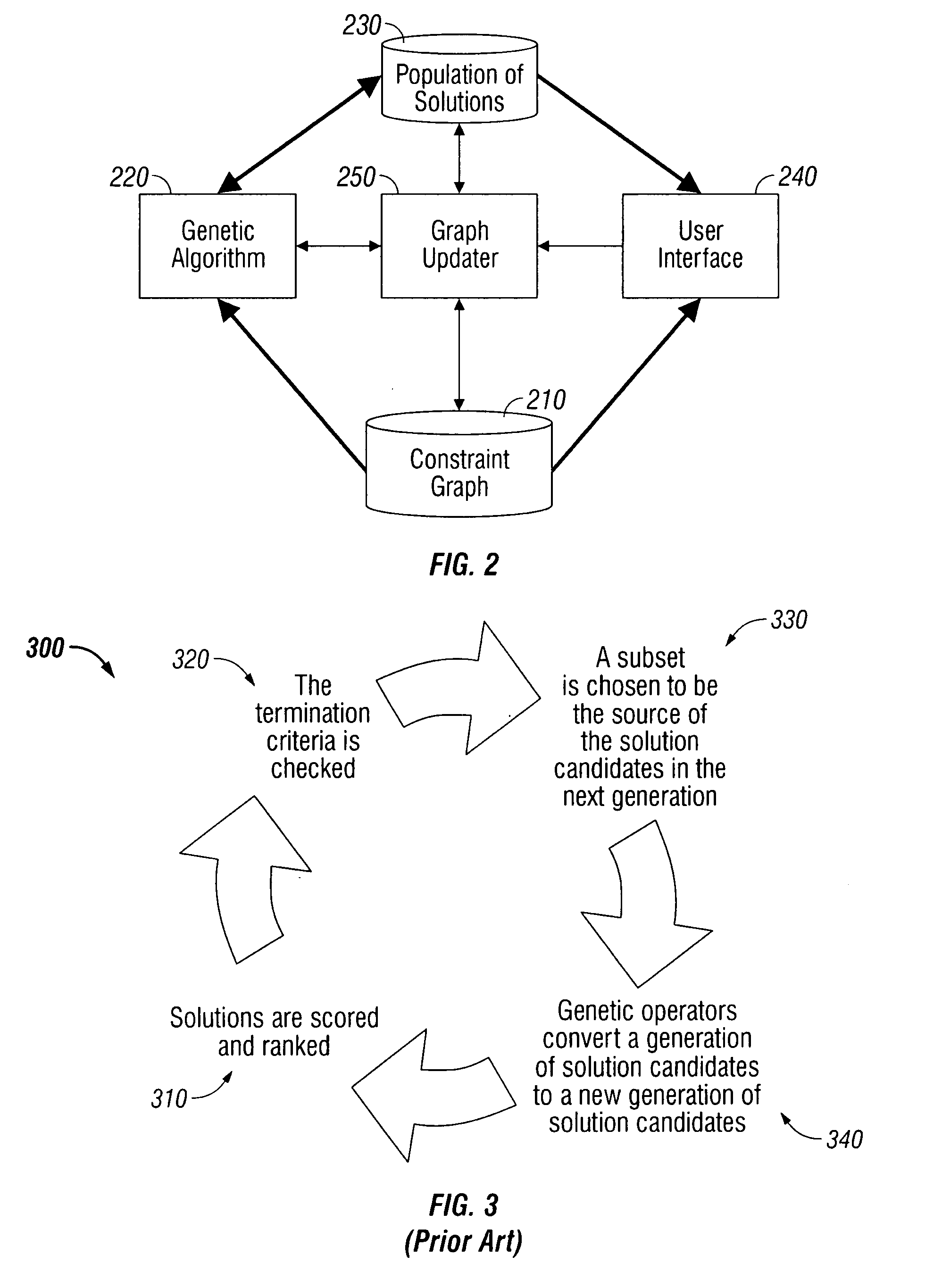
[0009]In an alternative embodiment, a system is provided for solving an optimization problem having dynamic constraints, comprising means for retrievably storing a constraint graph corresponding to the plurality of dynamic constraints, means for retrievably storing a plurality of solutions to the optimization problem, wherein each one of the plurality of solutions corresponds to a connected subgraph of the constraint graph, user interface means for outputting one or more of the plurality of solutions, user interface means for receiving a constraint graph modification, means for implementing the constraint graph modification in real time, and genetic algorithm means for optimizing solutions to the optimization problem.

Problems solved by technology

The highest-ranked solution that is displayed at the end of each generation may be the best solution for that generation of solution candidates, but it may not be the optimal solution for the current state of the constraint graph.
If there are no available unallocated missions the genetic operator fails.
If there are no available units that fly A, the genetic operator fails.
If there are no time objects available for U, the genetic operator fails.
If the mission is not flyable, the genetic operator fails.
It may be the case that delays or excessive fuel consumption over the target area may require replanning in order to satisfy the needs of the fighter or bomber.
There can never be more packages than targets nor missions and in a solution many genes have unused package data.
Although it would be possible to remove an irrelevant node from the graph, that solution is less desirable because the node may become relevant after the passage of time or other developments.
The trailing edge of the planning window presents other difficulties, however.

Method used


Image

  • Method and system for solving an optimization problem with dynamic constraints
  • Method and system for solving an optimization problem with dynamic constraints
  • Method and system for solving an optimization problem with dynamic constraints

Examples


Embodiment Construction

[0021]The genetic algorithm in an embodiment represents each potential solution to an optimization problem as a chromosome, and a constraint graph is used to help ensure that all chromosomes correspond to feasible solutions. The optimization problem in an embodiment is the scheduling of air missions as in, e.g., creation of an ATO, and each chromosome, in an embodiment, represents a set of air missions.

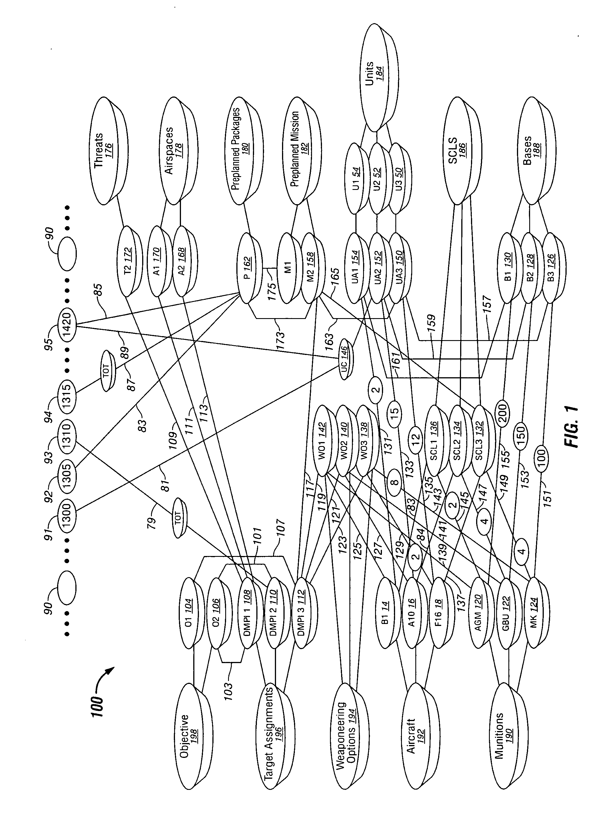
[0022]Identifying whether a particular solution is feasible or infeasible is a constraint satisfaction problem that can be described by a constraint network. A constraint network is a triple in which is a finite set of variables X={X0, X1, . . . , Xn} with respective domains D={D0, D1, . . . , Dn} containing the possible values for each variable. C={C0, C1, . . . , Cn} is the set of all constraints where each constraint Ci is a relation that imposes a limitation on the values that a variable, or a combination of variables, may be assigned to. A constraint network can be represented a...


PUM


Abstract

A method and system for solving an optimization problem comprising a plurality of dynamic constraints. A genetic algorithm is used to iteratively generate potential solutions to the problem. A constraint graph is used to model the plurality of dynamic constraints, and any potential solution that does not correspond to a connected subgraph of the constraint graph is infeasible and discarded. Real-time changes in dynamic constraints are incorporated by modification of the constraint graph between iterations of the genetic algorithm. An exemplary embodiment comprising the scheduling of air missions is presented.

Description

GOVERNMENT LICENSE RIGHTS[0001]This invention was made with Government support under Contract No. FA8750-06-C-0025 awarded by the United States Air Force Research Laboratory. The Government has certain rights in the invention.BACKGROUND[0002]A genetic algorithm is a heuristic method based on the mechanics of natural selection and genetics that is a powerful tool for finding solutions to optimization problems, i.e., finding optimal (or more optimal) feasible solutions to a problem under a set of objectives and constraints. A solution is “feasible” if it complies with all constraints binding the different variables, and infeasible if it does not comply with all constraints binding the different variables. An “optimal” solution is the most “fit” of the feasible solutions, where the fitness of a solution is determined by how it is scored by a fitness function. In other words, solution A is more fit—better—than solution B under a particular fitness function F if the fitness function F gi...

Claims


Application Information

Patent Timeline
Patent Type & Authority Applications(United States)
IPC IPC(8): G06F15/18
CPCG06N3/126
Inventor TAYLOR, DARRINALFORD, LEE
Owner 21ST CENTURY TECH
Learn More