
Position Tracking Device, Position Tracking Method, Position Tracking Program and Mixed Reality Providing System

a technology of positioning tracking and positioning target, which is applied in the direction of instruments, toys, and image enhancement, etc., can solve the problems of limiting the range of positioning tracking devices, and requiring more space than a measurement target. to achieve the effect of accurately detecting the position of a target object on the screen

Inactive Publication Date: 2008-10-30
UNIVERSITY OF ELECTRO-COMMUNICATIONS
View PDF0 Cites 139 Cited by
  • Summary
  • Abstract
  • Description
  • Claims
  • Application Information

AI Technical Summary

Benefits of technology

[0009]The present invention has been made in view of the above points and is intended to provide: a position tracking device, position tracking method and position tracking program that are simpler than the conventional ones but can accurately detect the position of a target object of the real environment on a screen or a display target; and a mixed reality providing system that uses the position tracking method.

Problems solved by technology

However, the above position tracking device that includes the optical system uses a camera, which requires more space than a measurement target does.
In addition, the above position tracking device cannot measure a portion that is out of the scope of the camera.
This limits a range the position tracking device can measure.
However, it is difficult for the position tracking device that includes the magnetic sensor system to increase the number of sensors that can measure at the same time.
Moreover, there are various problems: If there are plenty of metals in the measurement target space, this may dramatically decrease the accuracy of detection.
However, if there is a shield material between the transmitter and the receiver, this may make it difficult for the position tracking device that includes the ultrasonic sensor system to measure.

Method used


Image

  • Position Tracking Device, Position Tracking Method, Position Tracking Program and Mixed Reality Providing System
  • Position Tracking Device, Position Tracking Method, Position Tracking Program and Mixed Reality Providing System
  • Position Tracking Device, Position Tracking Method, Position Tracking Program and Mixed Reality Providing System

Examples


Embodiment Construction

[0049]An embodiment of the present invention will be described in detail with reference to the accompanying drawings.

(1) Principle of Position Detection

(1-1) Position Tracking Device

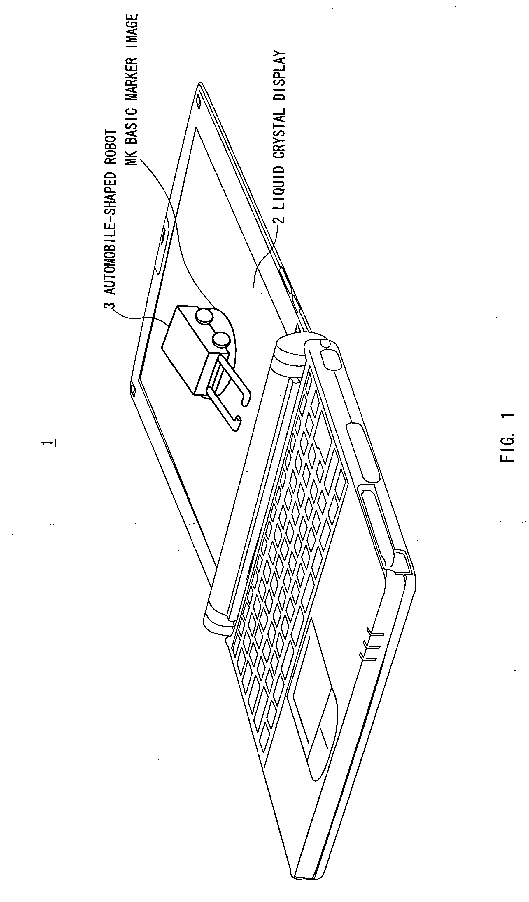
[0050]In the present embodiment, the following describes the principle of position detection upon which a position tracking device according to the present invention is based. As shown in FIG. 1, a notebook-type personal computer (also referred to as a “note PC”) 1, which is used as a position tracking device, is designed to display, in order to detect the change of position of an automobile-shaped robot 3 on a screen of a liquid crystal display 2, a basic maker image MK (described later) on the screen such that the basic marker image MK faces the automobile-shaped robot 3.

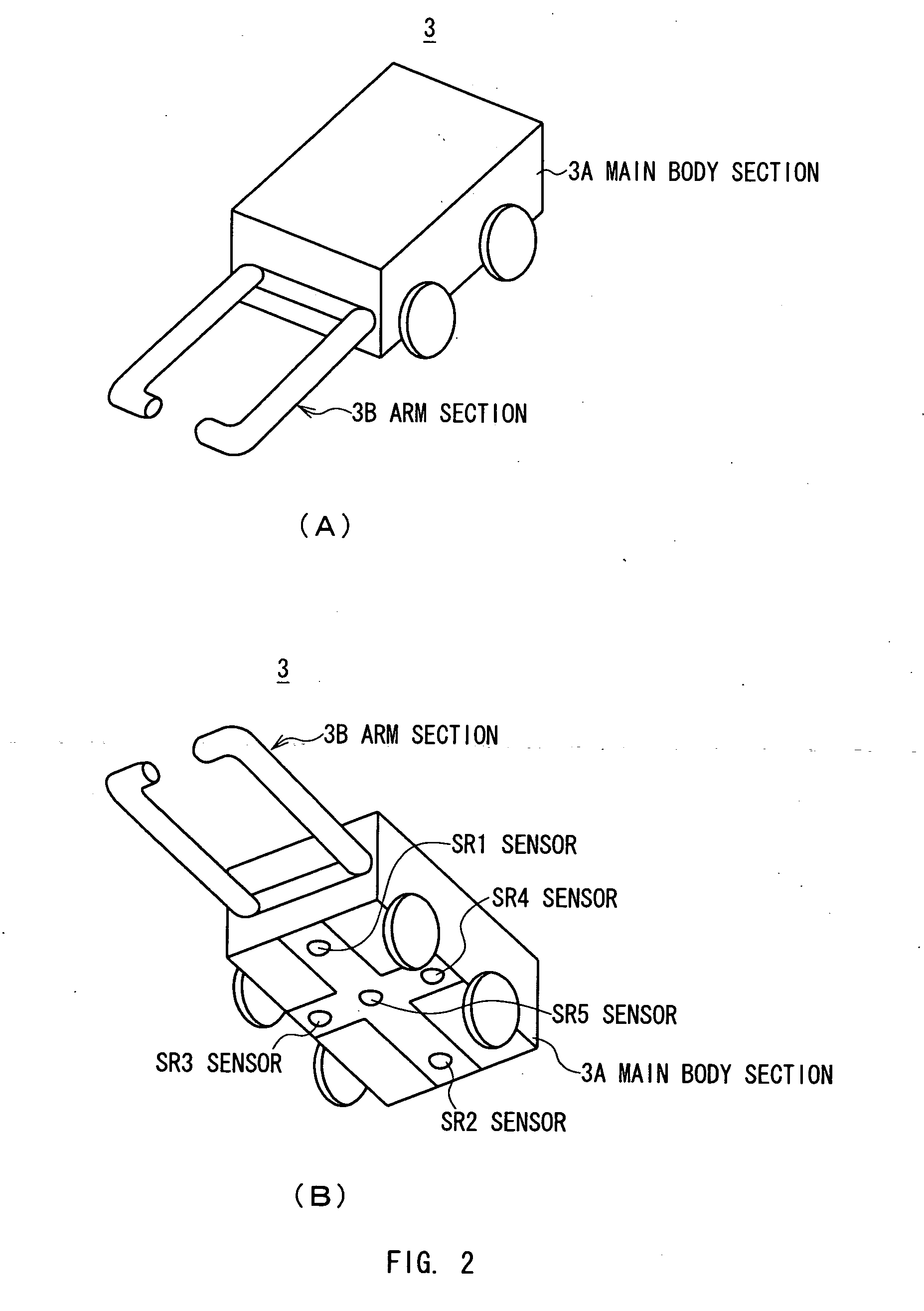
[0051]The automobile-shaped robot 3 includes, as shown in FIG. 2(A), four wheels on the left and right sides of a main body section 3A that is substantially in the shape of a rectangular parallelepiped. The automobile-shaped robot 3 al...


PUM


Abstract

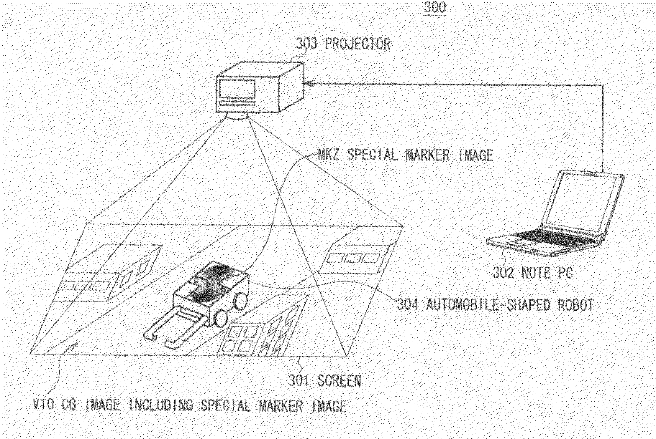
The present invention has a simpler structure than before and is designed to precisely detect the position of a real environment's target object on a screen. The present invention generates a special marker image MKZ including a plurality of areas whose brightness levels gradually change in X and Y directions, displays the special marker image MKZ on the screen of a liquid crystal display 2 such that the special marker image MKZ faces an automobile-shaped robot 3, detects, by using sensors SR1 to SR4 provided on the automobile-shaped robot 3 for detecting the change of brightness level of position tracking areas PD1A, PD2A, PD3 and PD4 of the special marker image MKZ in the X and Y directions, the change of brightness level, and then detects the position of the automobile-shaped robot 3 on the screen of the liquid crystal display 2 by calculating, based on the change of brightness level, the change of relative coordinate value between the special marker image MKZ and the automobile shaped robot 3.

Description

TECHNICAL FIELD[0001]The present invention relates to a position tracking device, position tracking method, position tracking program and mixed reality providing system, and, for example, is preferably applied for detecting a target object of the real environment that is physically placed on a presentation image on a display and is preferably applied to a gaming device and the like that use that method of detection.BACKGROUND ART[0002]Conventionally, there is a position tracking device that detects position by using an optical system, a magnetic sensor system, an ultrasonic sensor system and the like. Theoretically, if it uses an optical system, the measuring accuracy is determined by the pixel resolution of a camera and an angle between optical axes of the camera.[0003]Accordingly, the position tracking device that includes the optical system uses brightness information and shape information of a marker at the same time in order to improve the accuracy of detection (see Patent Docu...

Claims


Application Information

Patent Timeline
Patent Type & Authority Applications(United States)
IPC IPC(8): G06K9/78
CPCA63H17/395G06T7/0042G06T2207/10016G06T2207/30204G06T2207/30248G06T7/73G01B11/00G06T19/20
Inventor SUGIMOTO, MAKINAKAMURA, AKIHIRONII, HIDEAKIINAMI, MASAHIKO
Owner UNIVERSITY OF ELECTRO-COMMUNICATIONS
Learn More