
Rear obstruction detection

a detection and obstruction technology, applied in the field of rear obstruction detection, can solve problems such as vehicle damag

Active Publication Date: 2008-10-30
MOBILEYE VISION TECH LTD
View PDF18 Cites 214 Cited by
  • Summary
  • Abstract
  • Description
  • Claims
  • Application Information

AI Technical Summary

Benefits of technology

[0010]The term “immediate vicinity” in reference to a vehicle typically includes the ground less than one meter from the vehicle edge in the direction of intended motion, e.g reverse motion, or in other embodiments (e.g. for cameras of field of view 180 degrees or more) the term “immediate vicinity” induces zero distance from the vehicle edge in the direction of intended motion in which the camera also views straight down.

Problems solved by technology

Motor vehicles, especially sport utility vehicles (SUV), pick-up trucks and off-road vehicles typically have a “blind” zone behind the vehicles which is a contributing cause for accidents when the vehicles are driven in reverse.
Motor vehicle accidents involving vehicles being driven in reverse cause vehicle damage there is a collision with typically low obstructions, e.g. walls and poles, and serious accidents involving children.
Rear looking camera systems which provide the driver additional visibility using an attached monitor, for example parking assist systems, and blind spot detection systems are known in the industry, but unlike the forward looking camera systems, these reverse looking camera systems provide the driver images on the monitor without providing any analysis of the images or warning of the existence of an obstacle behind the vehicle or of an expected collision with an obstacle.

Method used


Image

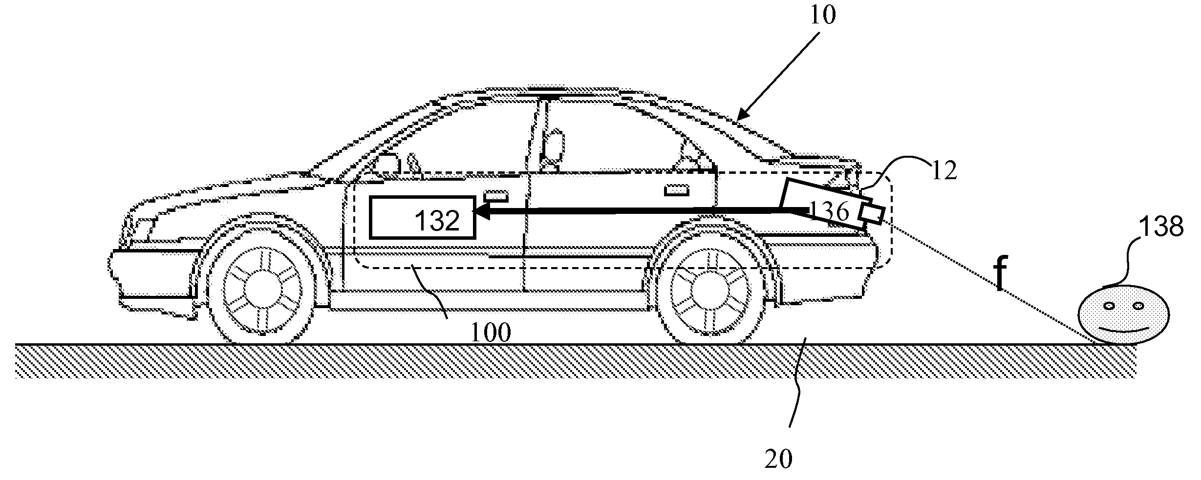
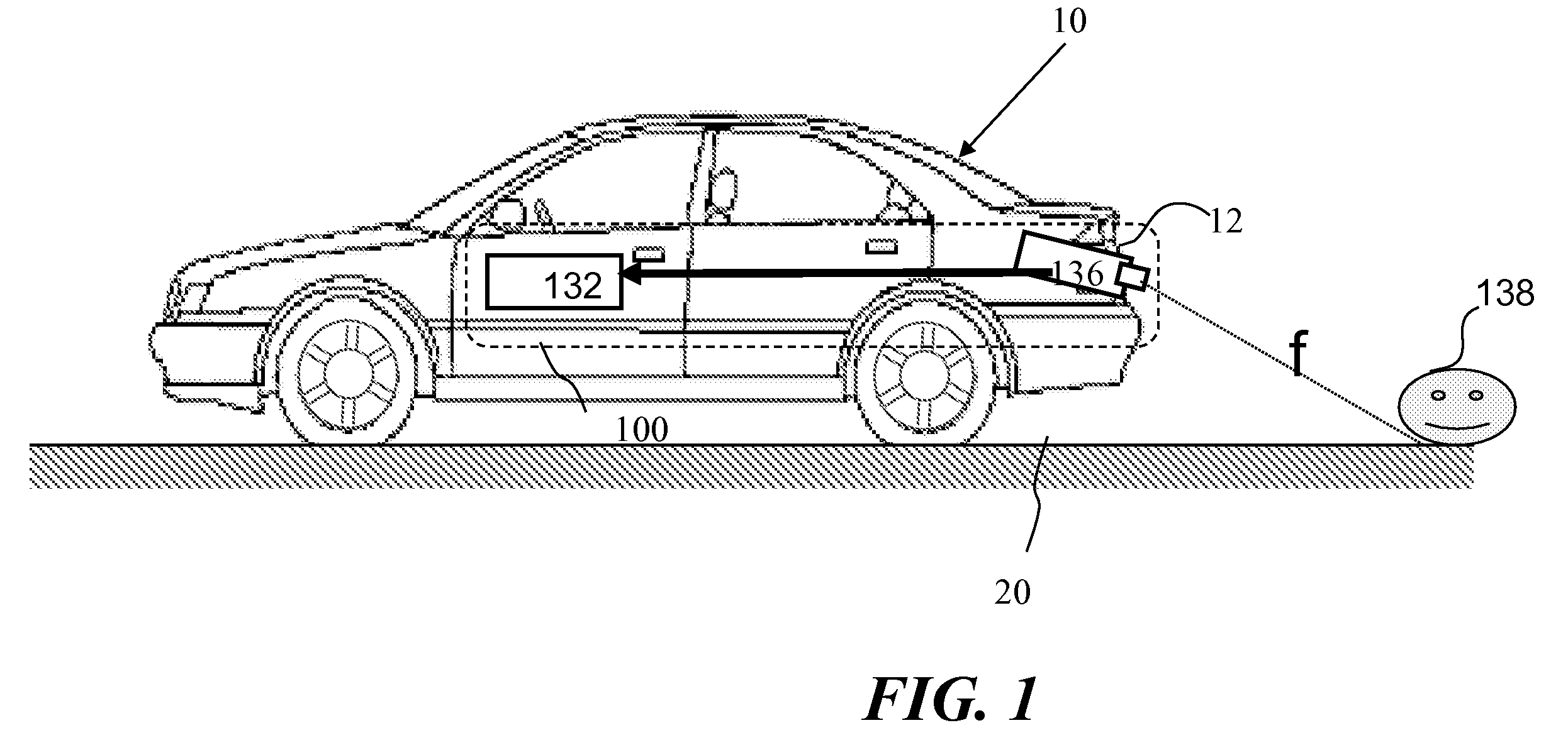
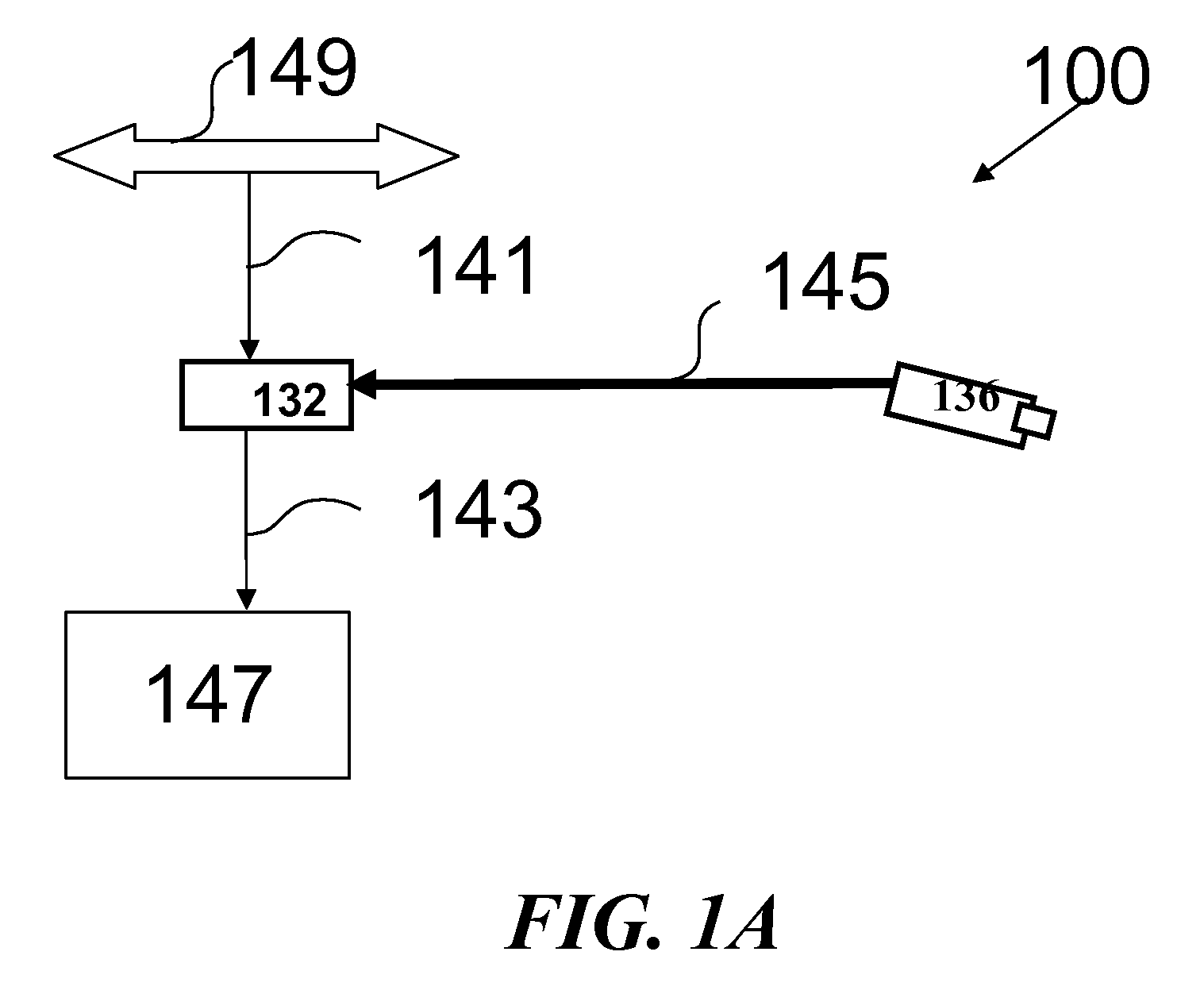
  • Rear obstruction detection
  • Rear obstruction detection
  • Rear obstruction detection

Examples


Embodiment Construction

[0027]Reference will now be made in detail to embodiments of the present invention, examples of which are illustrated in the accompanying drawings, wherein like reference numerals refer to the like elements throughout. The embodiments are described below to explain the present invention by referring to the figures.

[0028]Before explaining embodiments of the invention in detail, it is to be understood that the invention is not limited in its application to the details of design and the arrangement of the components set forth in the following description or illustrated in the drawings. The invention is capable of other embodiments or of being practiced or carried out in various ways. Also, it is to be understood that the phraseology and terminology employed herein is for the purpose of description and should not be regarded as limiting.

[0029]While the discussion herein is directed toward application of the present invention to a rear viewing system mounted on a vehicle, e.g. automobile...


PUM


Abstract

A method is provided using a system mounted in a vehicle. The system includes a rear-viewing camera and a processor attached to the rear-viewing camera. When the driver shifts the vehicle into reverse gear, and while the vehicle is still stationary, image frames from the immediate vicinity behind the vehicle are captured. The immediate vicinity behind the vehicle is in a field of view of the rear-viewing camera. The image frames are processed and thereby the object is detected which if present in the immediate vicinity behind the vehicle would obstruct the motion of the vehicle. The processing is preferably performed in parallel for a plurality of classes of obstructing objects using a single image frame of the image frames.

Description

CROSS REFERENCE TO RELATED APPLICATIONS[0001]The present application claims priority under 35 U.S.C. §119(e) from U.S. provisional application 60 / 914,859 filed Apr. 30, 2007, the disclosure of which is incorporated entirely herein by reference.FIELD AND BACKGROUND[0002]The present invention relates to vehicle warning systems, and more particularly to a system and method for detection of objects behind the vehicle and classification of the objects.[0003]Motor vehicles, especially sport utility vehicles (SUV), pick-up trucks and off-road vehicles typically have a “blind” zone behind the vehicles which is a contributing cause for accidents when the vehicles are driven in reverse. The “blind” zone cannot be viewed directly by the driver nor with the use of the vehicle mirrors. Motor vehicle accidents involving vehicles being driven in reverse cause vehicle damage there is a collision with typically low obstructions, e.g. walls and poles, and serious accidents involving children.[0004]In...

Claims


Application Information

Patent Timeline
Patent Type & Authority Applications(United States)
IPC IPC(8): H04N7/18
CPCB60R2300/30B60R2300/404G06K9/00805B60R2300/8093H04N7/183B60R2300/806G06V20/58
Inventor STEIN, GIDEON
Owner MOBILEYE VISION TECH LTD
Learn More