
Step stool

a step stool and stool technology, applied in the field of step stool, can solve the problems of step stool scratching cabinetry and flooring,

Inactive Publication Date: 2008-10-30
TATUM MARY K +1
View PDF9 Cites 27 Cited by
  • Summary
  • Abstract
  • Description
  • Claims
  • Application Information

AI Technical Summary

Benefits of technology

[0009]The present invention provides a step stool for storing underneath a cabinet and extending therefrom when in use. The step stool includes a platform member for supporting a user. The platform member is manufactured from a first predetermined material and has a first predetermined size and a first predetermined shape. A means is operably disposed on at least one of a bottom portion of such platform member and at least one side of such platform member at a first predetermined location thereon for facilitating movement of the step stool such that the step stool may be extended from underneath such cabinet for use and may be returned to a position underneath such cabinet for storage.OBJECTS OF THE INVENTION
[0010]It is, therefore, one of the primary objects of the present invention to provide an easy to use step stool which is storable in a location convenient to a user.
[0011]Another object of the present invention is to provide a step stool which is stored below a cabinet and easily slides out from under such cabinet when in use and slides back under such cabinet for storage.
[0013]Still another object of the present invention is to provide a wheeled step stool; the wheels stabilize and refrain from moving upon such step stool bearing a predetermined amount of weight.
[0014]Yet another object of the present invention is to provide a step stool that can be rolled out from under a cabinet to provide a step stool having at least one step.
[0015]An additional object of the present invention is to provide a step stool which can be pulled out from under a cabinet and pushed back under such cabinet and which may include a non-slip gripping surface on the stepping surface thereof.

Problems solved by technology

This can often be inconvenient since the step stool may be stored in an inconvenient location and may also be heavy and cumbersome.
Additionally the step stool may scratch cabinetry and flooring.

Method used


Image

  • Step stool
  • Step stool
  • Step stool

Examples


Embodiment Construction

, particularly, when such description is taken in conjunction with the attached drawing figures and with the appended claims.

BRIEF DESCRIPTION OF THE DRAWINGS

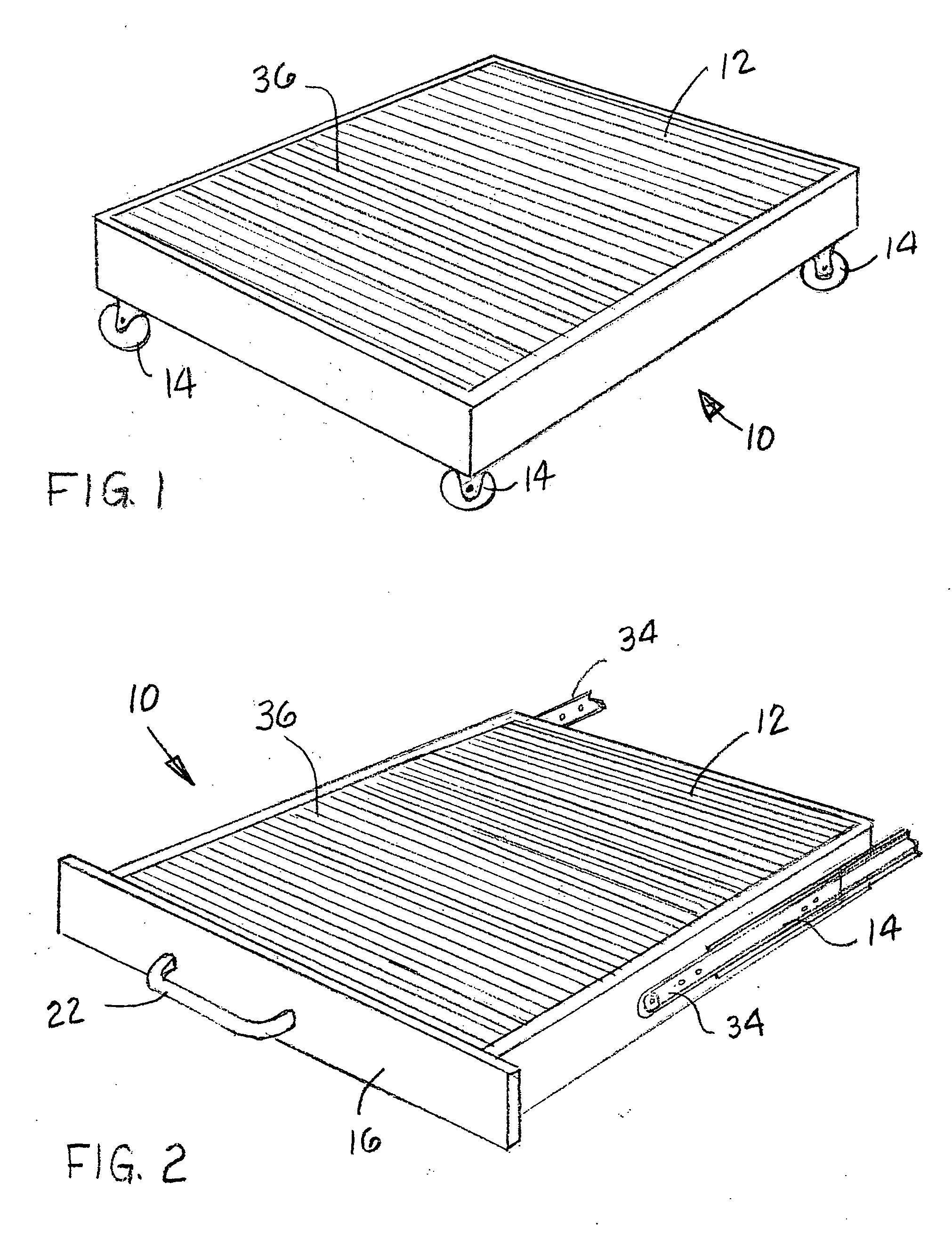
[0017]FIG. 1 is a partial perspective view of the invention according to one embodiment of the invention wherein such step stool includes wheels for facilitating movement and has a non-slip surface.

[0018]FIG. 2 is a partial perspective view of the invention according to one embodiment of the invention in which such step stool is securable to a cabinet by drawer slides.

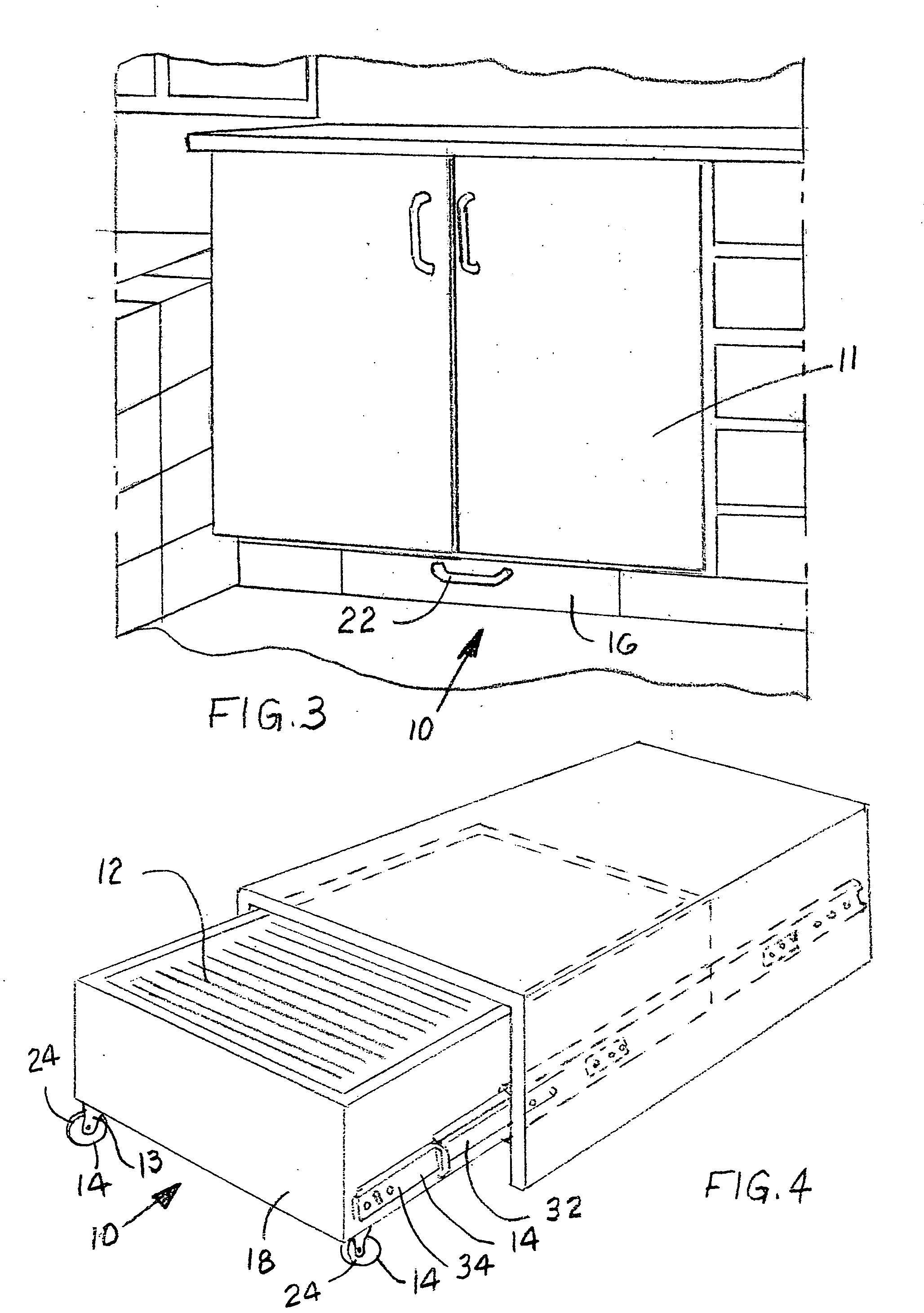
[0019]FIG. 3 is a partial perspective view of the invention according to one embodiment of the invention in which such step stool is being housed under cabinetry and has a front panel with a handle.

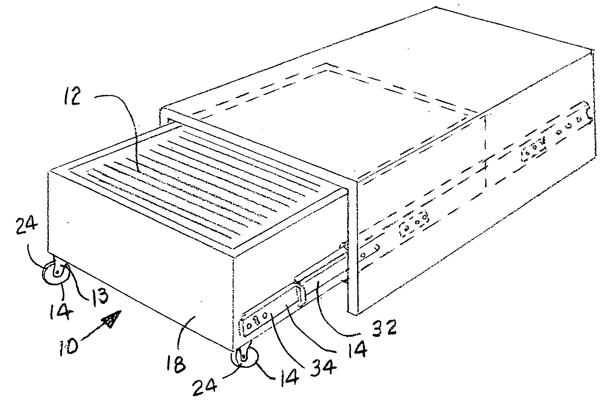
[0020]FIG. 4 is a partial perspective view of the invention according to one embodiment of the invention in which the step stool has been attached to cabinetry using drawer slides.

[0021]FIG. 5 is a partial perspective view of the invention according to one embodiment of...


PUM


Abstract

A step stool for storing underneath a cabinet and extending therefrom when in use is provided. Such step stool includes a platform member for supporting a user. Such platform member being manufactured from a first predetermined material and having a first predetermined size and a first predetermined shape. A mechanism is operably disposed on at least one of a bottom portion of such platform member and at least one side of such platform member at a first predetermined location thereon for facilitating movement of the step stool such that the step stool may be extended from underneath such cabinet for use and may be returned to a position underneath such cabinet for storage.

Description

CROSS REFERENCE TO RELATED APPLICATION[0001]This patent application is related to and claims priority from U.S. Provisional Patent Application Ser. No. 60 / 926,132 filed Apr. 25, 2007.FIELD OF THE INVENTION[0002]The present invention relates, in general, to step stools and, more particularly, this invention relates to step stools which may be stored underneath cabinets.BACKGROUND OF THE INVENTION[0003]Prior to the conception and development of the present invention, step stools, as are generally well known in the prior art, have been used to permit users to obtain things that would otherwise be unreachable. Generally, step stools are transported to the necessary location, unfolded or simply set in place and the user steps up and reaches for the needed item. This can often be inconvenient since the step stool may be stored in an inconvenient location and may also be heavy and cumbersome. Additionally the step stool may scratch cabinetry and flooring. A need exists for a step stool whi...

Claims


Application Information

Patent Timeline
Patent Type & Authority Applications(United States)
IPC IPC(8): E06C1/00A47B88/04A47B77/10
CPCA47C12/00E06C1/005
Inventor TATUM, MARY K.BARTLETT, TAMARA A.
Owner TATUM MARY K
Learn More