
Protective cover and tool splash for vehicle components

a technology for vehicle components and protective covers, applied in the field of vehicle components, can solve the problems of time-consuming and cost-abortive repair or replacement of damaged components, additional associated costs in relation to removal and reapplication of protective covers, and achieve the effects of reducing or eliminating costs, reducing time consumption and increasing durability

Inactive Publication Date: 2008-10-30
THE BOEING CO
View PDF18 Cites 1 Cited by
  • Summary
  • Abstract
  • Description
  • Claims
  • Application Information

AI Technical Summary

Benefits of technology

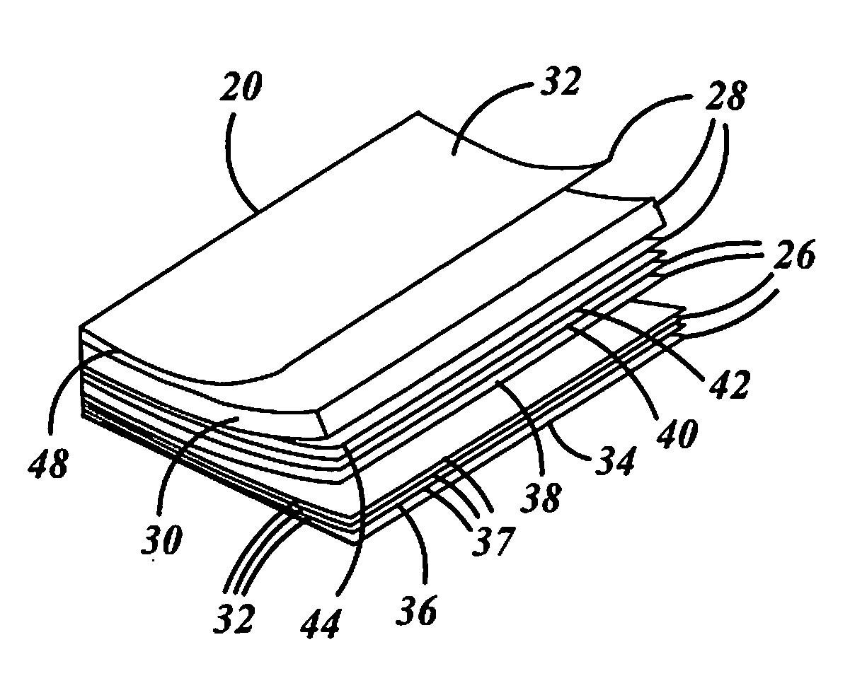
[0013]The embodiments of the present invention provide several advantages. One such advantage is the provision of a cost effective method of forming a protective cover for a vehicle component that contains materials that are similar to that of the vehicle component. In using similar materials, the protective cover has similar fire resistant characteristics as the vehicle component, is lightweight, and as such minimizes or eliminates the need to be removed for testing procedures. Also, the protective cover provides increased durability and is resistant to undesired intrusions, such as punctures. The protective covers minimize the manufacturing time and provide improved esthetics in comparison to previous protective covers.
[0014]Another advantage provided by an embodiment of the present invention, is the provision of forming a splash from similar materials used in forming a vehicle component, and the same mold dies without disrupting production. The splash is lightweight and allows for the quick and economically effective forming of down stream part supports or molds, such as support pedestals and fixtures, for the production of down stream parts. Also, the stated technique provides a splash that has reduced thermal energy retention characteristics, thus allowing quicker and easier handling.

Problems solved by technology

Repair or replacement of damaged components can be time consuming and cost abortive.
It is understood that the use of the protective covers is costly.
This is due not only to the costs related to the manufacturing and purchasing of the covers, but also to the application and removal of the covers to and from the respective components.
Additional associated costs also exist in relation to the removal and reapplication of the covers for flight-testing.
It is also understood that the effectiveness of the flame retardant spray tends to diminish over time.
The use of a fire retardant plastic in replacement of the flame retardant spray has been considered and is also costly.
In addition, it is also costly to form tooling or molds for vehicle components.
The tools and molds can require tens-hundreds of hours to form, can be heavy, and can be difficult to handle.
The tools and molds when utilized tend to become hot and the thermal energy contained therein tends to dissipate slowly.
The vacuum form mold is often formed of solid blocks, which tend to be heavy.

Method used


Image

  • Protective cover and tool splash for vehicle components
  • Protective cover and tool splash for vehicle components
  • Protective cover and tool splash for vehicle components

Examples


Embodiment Construction

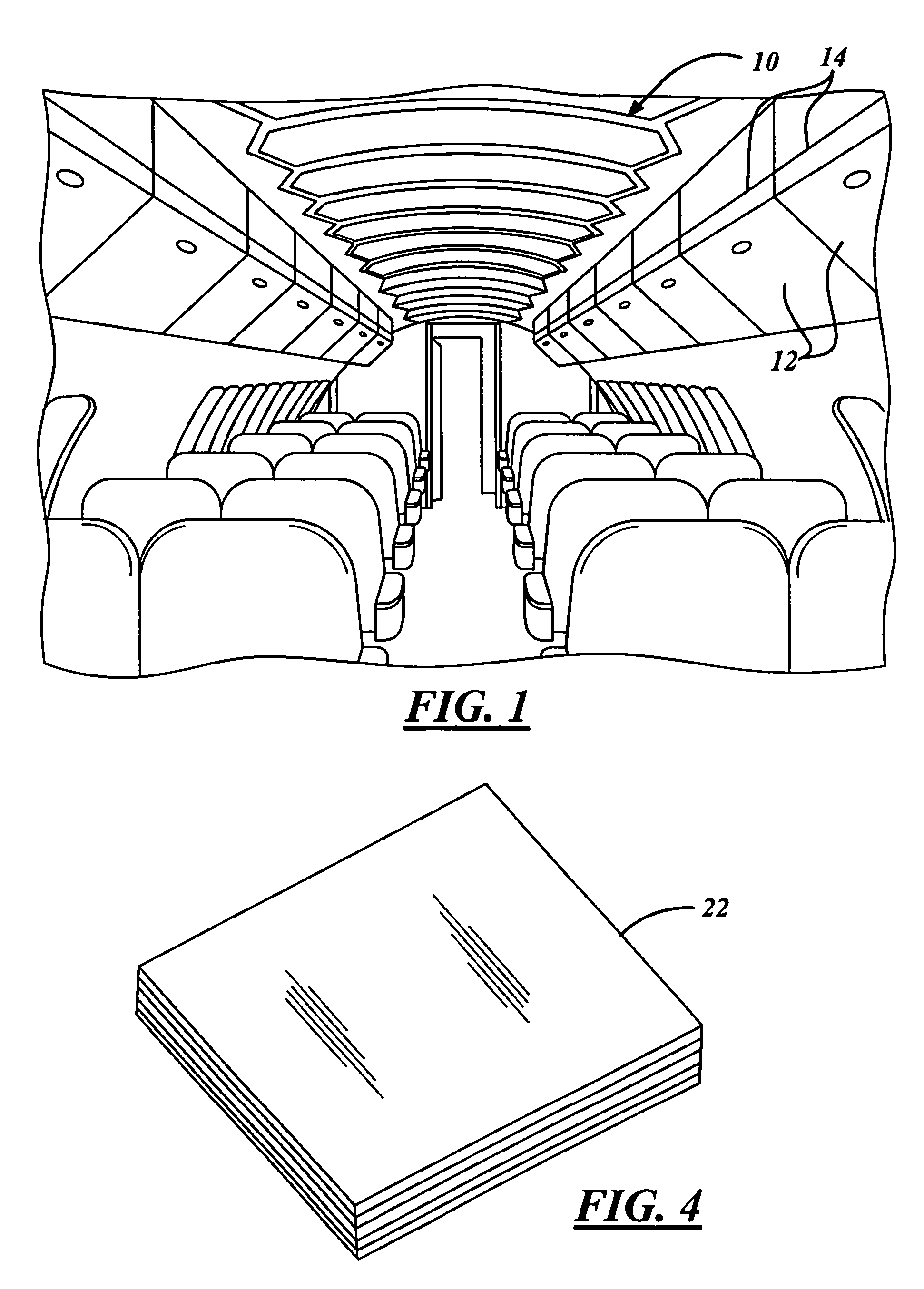
[0032]In the following Figures the same reference numerals will be used to refer to the same components. While the present invention is described primarily with respect to protective covers, splashes, and down stream parts, structures, and molds for various aircraft applications, the present invention may be applied in aeronautical applications, nautical applications, railway applications, automotive vehicle applications, and commercial and residential applications. The present invention may, for example, be applied to any part that requires matched mold dies for crushing composite parts. Also, a variety of other embodiments are contemplated having different combinations of the below described features of the present invention, having features other than those described herein, or even lacking one or more of those features. As such, it is understood that the invention can be carried out in various other suitable modes.

[0033]In the following description, various operating parameters ...


PUM

PropertyMeasurementUnit
timeaaaaaaaaaa
thickness T1aaaaaaaaaa
temperatureaaaaaaaaaa

Abstract

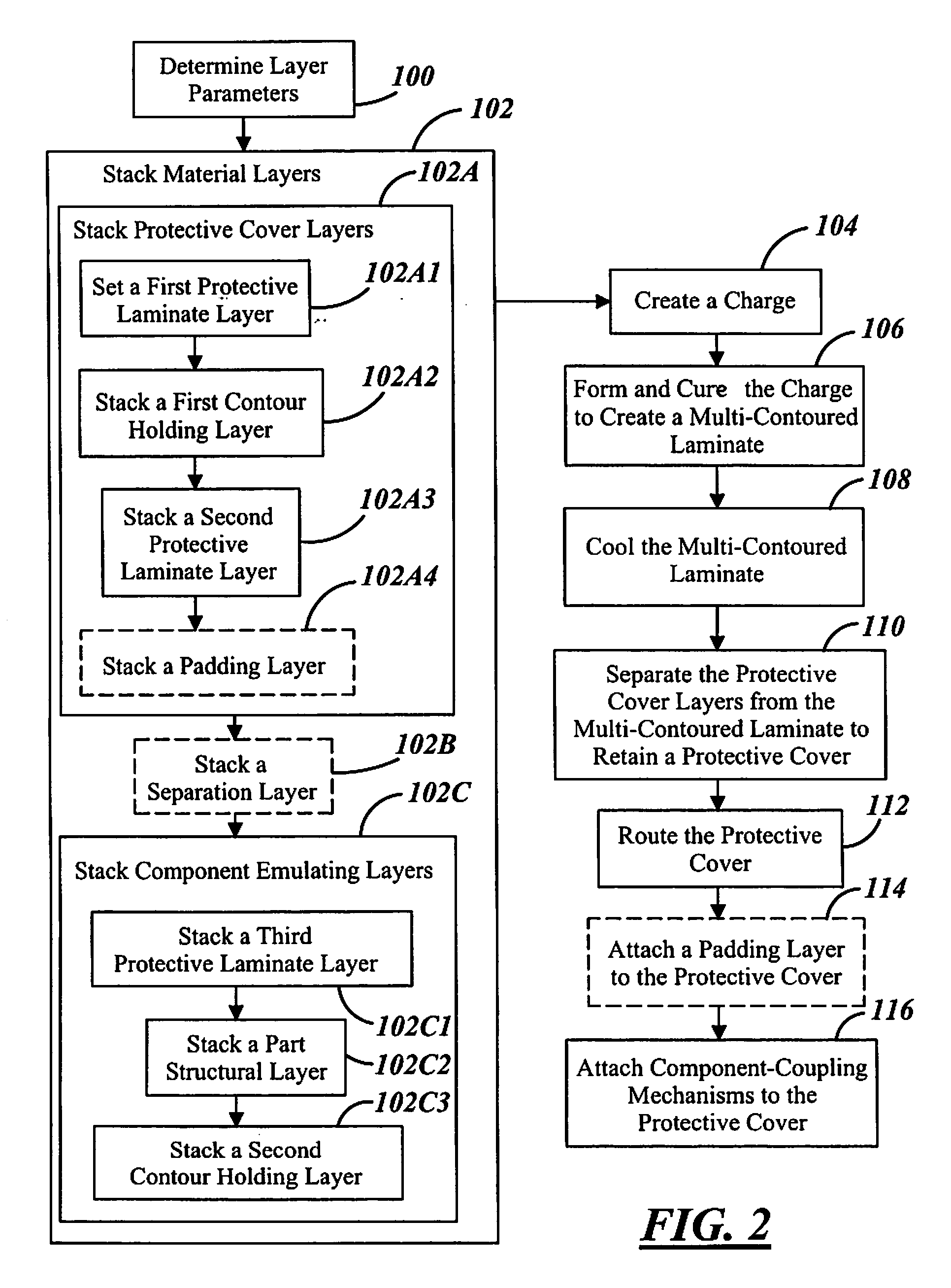
A method of manufacturing a protective cover (24) for a component of a vehicle includes assembling multiple layers to form a charge (22). The charge (22) is formed within a mold (50) of the component to form a multi-contoured laminate (58). The protective cover (24) is separated from the multi-contoured laminate (58). A method of forming a down stream part structure or mold (167) for a component includes assembling multiple layers to form a charge (78). The charge (78) is formed within an original mold of the component to form a multi-contoured laminate (76). A splash is separated from the multi-contoured laminate (76). A protective cover, such as the cover (24), is for a vehicle component and includes a contour holding layer (36) and a protective laminate layer (34). The contour holding layer (36) and the protective laminate layer (34) are formed within a mold of the vehicle component to form the protective cover.

Description

CROSS-REFERENCE TO RELATED APPLICATIONS[0001]This application is a division of application Ser. No. 10 / 907,786, filed Apr. 15, 2005, which is incorporated in its entirety herein by reference thereto.TECHNICAL FIELD[0002]The present invention is related generally to vehicle components, to protective covers of the vehicle components, and to vehicle component tools. More particularly, the present invention is related to methods of forming protective component covers and down stream parts, structures, and molds associated with vehicle components.BACKGROUND OF THE INVENTION[0003]During the manufacturing and assembly of an aircraft protective covers are utilized to prevent damage to aircraft components. Repair or replacement of damaged components can be time consuming and cost abortive. The protective covers are generally wrapped over and held via straps to the components of concern. The covers guard against bumping and undesired intrusion due to shifting, transporting, storing, and assem...

Claims


Application Information

Patent Timeline
Patent Type & Authority Applications(United States)
IPC IPC(8): B65D65/02
CPCB29C33/68Y10T428/24851B29C43/146B29C43/203B29C51/02B29C51/145B29C70/088B29C2043/023B29C2043/3644B29C2043/3657B29C2043/561B29C2791/001B29C2791/006B29K2105/06B29K2105/0854B29K2709/08B29L2009/00B29L2031/3041B29L2031/3076B32B3/12B32B5/02B32B5/024B32B25/08B32B25/14B32B27/12B32B27/304B32B27/34B32B37/18B32B38/1866B32B2250/05B32B2262/101B32B2307/3065B32B2307/536B32B2307/552B32B2307/554B32B2307/558B32B2307/718B32B2571/00B32B2605/00B32B2605/18B60R13/02B60R13/0225B60R2011/0075Y10T428/15Y10T428/24942Y10T428/24165Y10T428/24628Y10T428/24669Y10T428/24149B29C43/00
Inventor WIRRICK, JEFFREY T.CLOUD, MICHAEL J.
Owner THE BOEING CO
Learn More