Flush or near-flush flooring transitions

a technology of transitions and flooring, applied in the direction of structural elements, building components, roof coverings, etc., can solve the problems of difficulty in covering gaps formed, problems encountered with conventional edge moldings, etc., and achieve the effect of increasing the efficient use of materials and reducing inventory

Inactive Publication Date: 2008-10-30
PERGO
View PDF13 Cites 17 Cited by
  • Summary
  • Abstract
  • Description
  • Claims
  • Application Information

AI Technical Summary

Benefits of technology

[0012]The outward-facing surface of the first element may be formed as a single, unitary, monolithic surface that covers both the first and second arms. This outward-facing surface may be decorated, for example, with a laminate or a paper, such as a monochromatic or patterned décor, optionally impregnated with a resin, in order to increase its aesthetic value, or blend, to match or contrast with the floor panels. Preferably, the outward facing surface has incorporated therein at least one material to increase its abrasion resistance, such as hard particles of silica, alumina, diamond, silicon nitride, aluminum oxide, silicon carbide and similar hard particles, preferably particles having a Moh's hardness of at least approximately 2, more preferably at least approximately 4, and most preferably at least approximately 6. This outward-facing surface may also be covered with other types of coverings, such as foils (such as metal, paper or thermoplastic foils), paints or a variety of other decorative elements, including, but not limited to wood veneer, ceramic, metal, vinyl or other decorative materials.
[0015]When installed, the assembly is designed such that the at least two feet of the first element are inserted into corresponding grooves in separate tracks. As a result, an upper portion of the structure of the first element bridges the gap.
[0019]An adhesive, such as a glue, a microballoon adhesive, contact adhesive, or chemically activated adhesive including a water-activated adhesive, may be also positioned on any of the pieces of the assembly to either hold the assembly together or in place. Of course, such an adhesive is not necessary, but may enhance or supplement the fit and positioning of the assembly over the gap between the floor elements. Additionally, the adhesive may assist in creating a more air-tight or moisture-tight joint.
[0023]Through this invention, it is possible to reduce the profile height of the transition molding where it overlaps onto the surface of the finished floor or can be used as a flush, i.e., coplanar, structure. Such a flush surface can be formed without the need for any milling of a vertical edge of finished flooring, which is conventionally necessary when installing flush transition moldings. In some embodiments, the first element of the assembly can be substantially smaller, having a less visible width than conventional overlapping transitions, as disclosed by U.S. Pat. No. 6,860,074, herein incorporated by reference in its entirety. Such a smaller visible width makes the flooring transition less noticeable in doorways and increases the aesthetic appeal of the smooth and overall appearance of the finished flooring when the flooring is installed through passageways from one room to another.
[0026]The ease of installation of the assembly of the invention is accomplished by the elimination of any need to drill holes and apply fasteners in concrete subfloors or to fasten to wood subfloors with mechanical fasteners. The flush and near-flush surface is accomplished without the need for milling. These two time consuming labors, often requiring specialized tools, have been eliminated from many embodiments of the installation by the assembly of the invention.
[0027]Finally, while conventional flush flooring transitions require a different flooring transition height for each additional flooring thickness, the assembly of the invention can be adjusted for various flooring heights and thicknesses. This feature allows for the reduction of multiple SKU's (shop-keeper units), reducing inventory, and increasing the efficient use of materials.

Problems solved by technology

A problem is encountered, however, when flooring materials that are dissimilar in shape or texture are used.
For example, when a hard floor is placed adjacent a carpet, problems are encountered with conventional edge moldings placed therebetween.
Such problems include difficulty in covering the gap that may be formed between the floorings having different height, thickness or texture.

Method used


Image

  • Flush or near-flush flooring transitions
  • Flush or near-flush flooring transitions
  • Flush or near-flush flooring transitions

Examples


Embodiment Construction

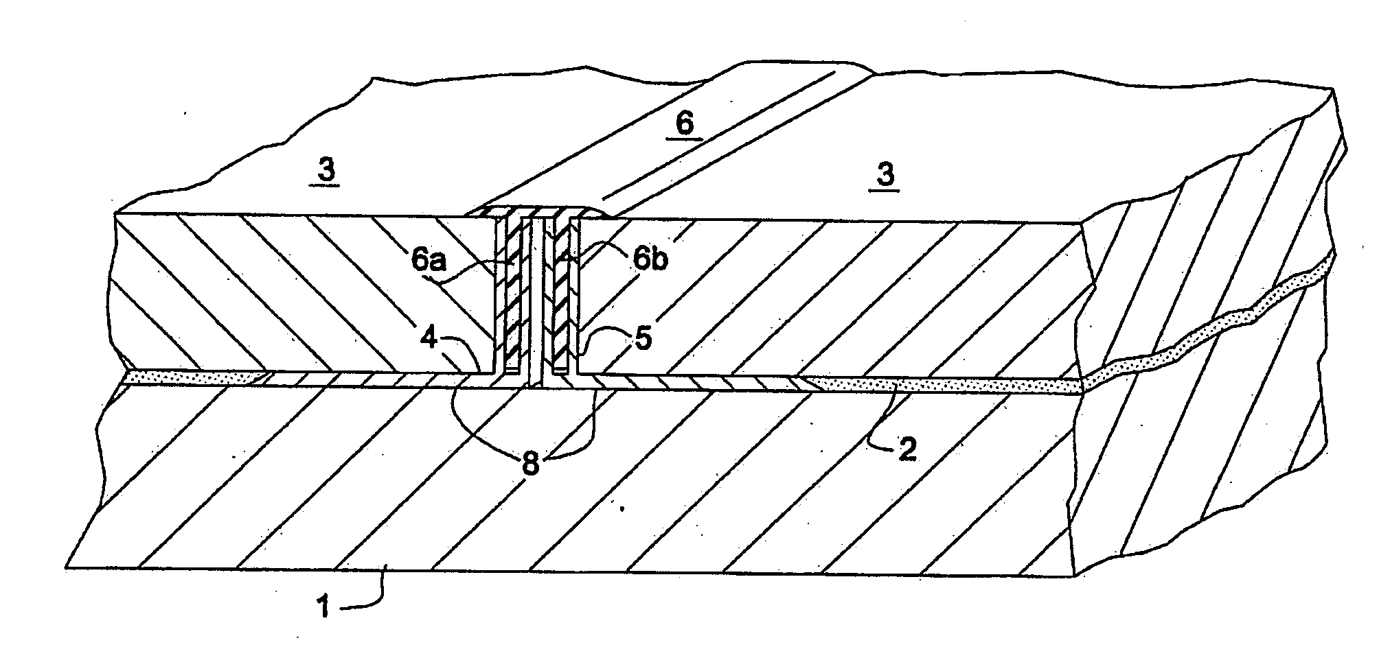
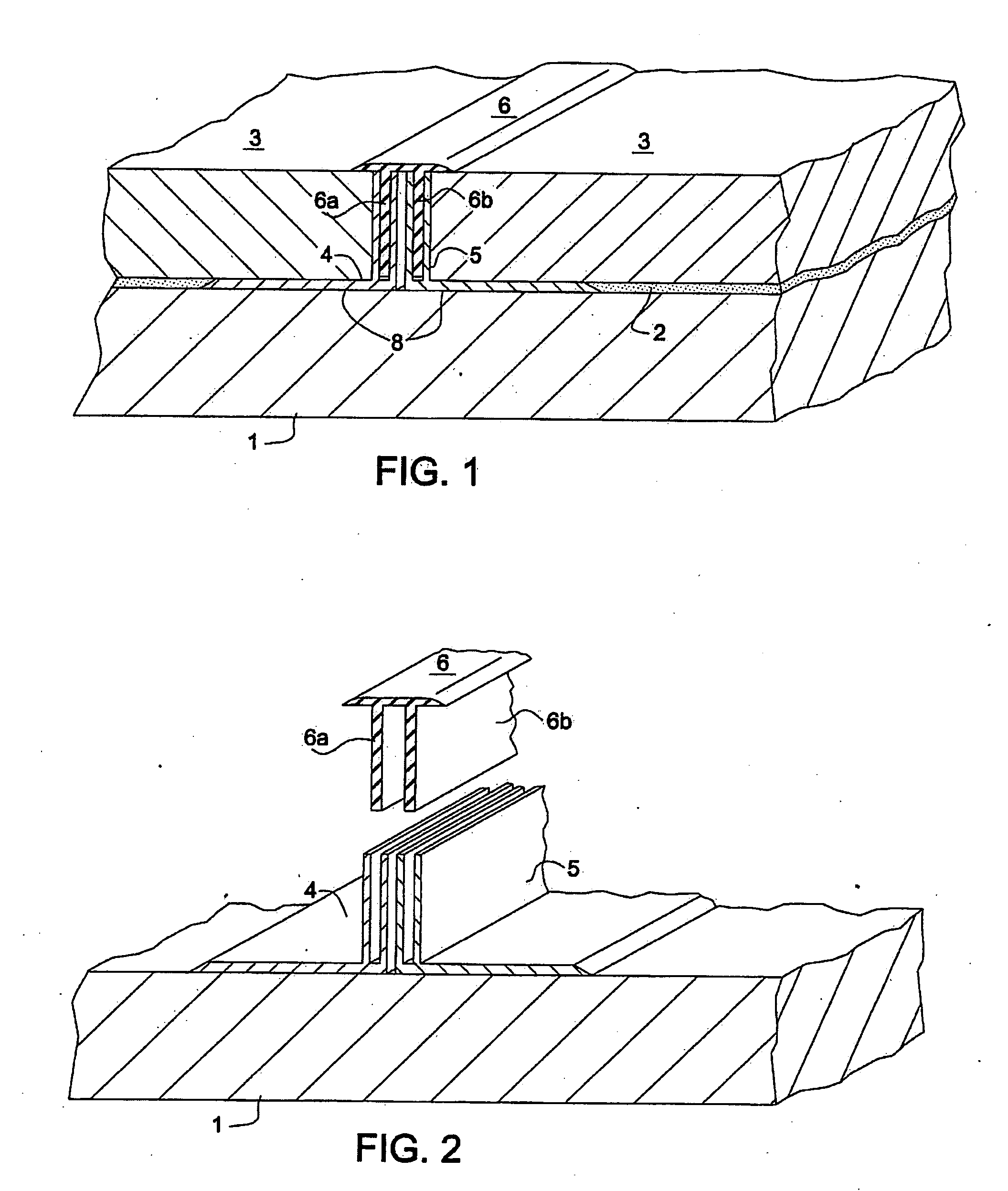
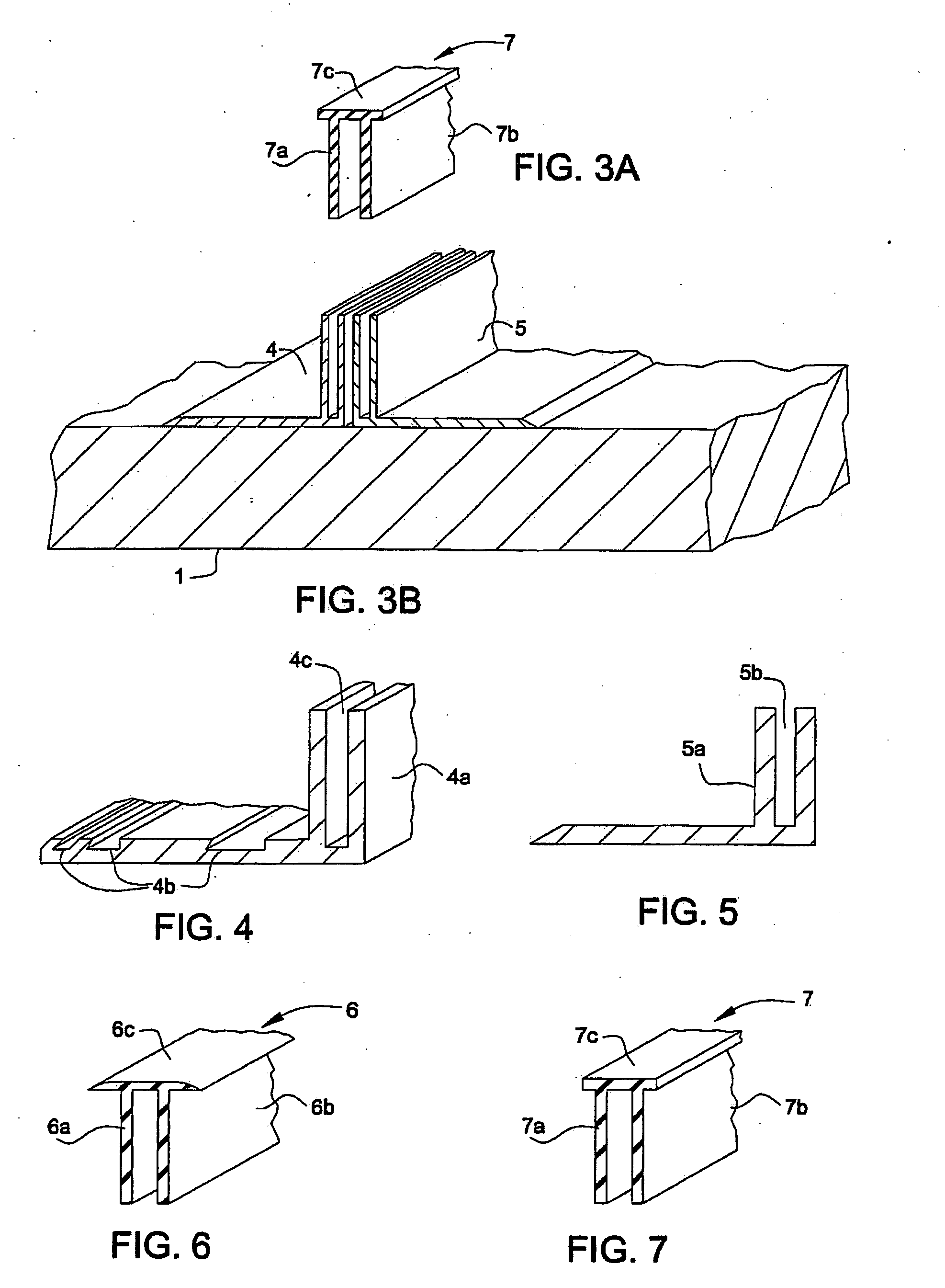
[0055]Generally, the invention is to be used above a subfloor 1, typically an underlayment 2, and between adjacent finished flooring elements 3. Underlayment 2 can be any type of conventional underlayment, e.g., foam, or film laid upon the subfloor or alternatively such underlayment may be affixed to flooring elements 3. As described herein, flooring elements 3 can, independently, be laminate panels, tiles (e.g., wood or ceramic), resilient flooring (e.g., vinyl), or carpet.

[0056]Two tracks, 4, 5 are preferably installed between subfloor 1 and one flooring element 3 to hold a T-molding in place. Tracks 4 and 5 can be attached to finished flooring 3, at horizontal surfaces thereof. It is additionally considered with the scope of the invention to attach track 4 to vertical edges of flooring elements 3. If finished flooring 3 has underlayment 2 affixed thereto, a portion of underlayment 2 is preferably removed, by, for example, being cut away, peeled back or shaved away, for direct con...


PUM


Abstract

The invention is a joint cover assembly for covering a gap adjacent an edge of a panel that covers a sub-surface, and a method of covering such a gap. The assembly can be installed to be a flush or near-flush arrangement with adjacent flooring elements.

Description

CROSS-REFERENCE RELATED APPLICATIONS[0001]This non-provisional application claims priority benefits of Provisional Application No. 60 / 858,335, filed on Nov. 13, 2006 which is herein incorporated by reference in its entirety.BACKGROUND[0002]1. Field of the Invention[0003]The invention relates to a one-piece structure which can be used to form flush and near-flush flooring transitions such as T-moldings, hard-surface reducers and end moldings, between or adjacent to flooring elements.[0004]2. Background of the Invention[0005]Hard surface floors, such as wood or laminate flooring have become increasingly popular. As such, many different types of this flooring have been developed. Generally, this type of flooring is assembled by providing a plurality of similar panels. The differing types of panels that have developed, of course, may have differing widths and thicknesses. The same is true when a laminate floor (often referred to as a “floating floor”) abuts another hard surface, such as...

Claims


Application Information

Patent Timeline
Patent Type & Authority Applications(United States)
IPC IPC(8): E04F15/00
CPCE04F15/02005E04F19/061E04F19/062E04F19/066E04F11/166
Inventor STANCHFIELD, OLIVERKORNFALT, SVENPIERCE, WILLIAM T.SMITH, PATRICK GEORGELA SERNA, SABADLARSSON, ROLANDJOHNSTON, WAYNE ROBERT
Owner PERGO
Why Eureka
Try Eureka