
System and method for selecting an intermediate frequency

a technology of intermediate frequency and system, applied in the direction of transmission, angle demodulation by oscillation sampling, electrical equipment, etc., can solve the problems of unsatisfactory image and particularly troublesome undesired imag

Inactive Publication Date: 2008-10-23
SILICON LAB INC
View PDF5 Cites 40 Cited by
  • Summary
  • Abstract
  • Description
  • Claims
  • Application Information

AI Technical Summary

Benefits of technology

[0004]In another exemplary embodiment, a method performed by a low intermediate frequency receiver is provided. The method includes determining a first power level of a first image in a

Problems solved by technology

As a result of the mixing, an undesired image occurs at an image frequency that can interfere with the target channel.
The undesired image can be particularly troublesome where strong spectral content is present at the image frequency.

Method used


Image

  • System and method for selecting an intermediate frequency
  • System and method for selecting an intermediate frequency
  • System and method for selecting an intermediate frequency

Examples


Embodiment Construction

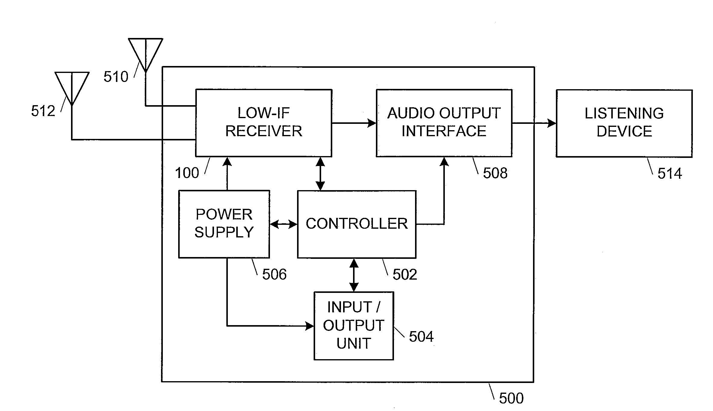
[0012]In the following Detailed Description, reference is made to the accompanying drawings, which form a part hereof, and in which is shown by way of illustration specific embodiments in which the invention may be practiced. In this regard, directional terminology, such as “top,”“bottom,”“front,”“back,”“leading,”“trailing,” etc., is used with reference to the orientation of the Figure(s) being described. Because components of embodiments of the present invention can be positioned in a number of different orientations, the directional terminology is used for purposes of illustration and is in no way limiting. It is to be understood that other embodiments may be utilized and structural or logical changes may be made without departing from the scope of the present invention. The following detailed description, therefore, is not to be taken in a limiting sense, and the scope of the present invention is defined by the appended claims.

[0013]As described herein, an integrated low power, l...


PUM


Abstract

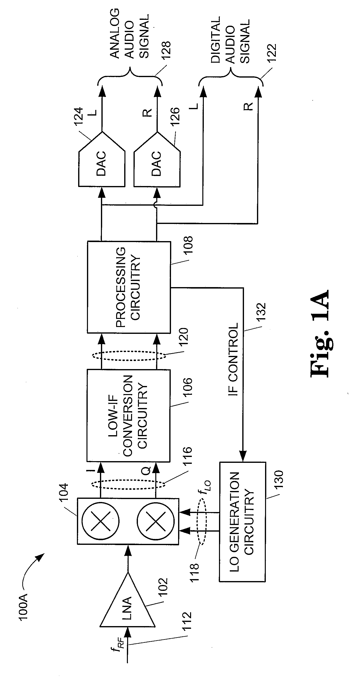
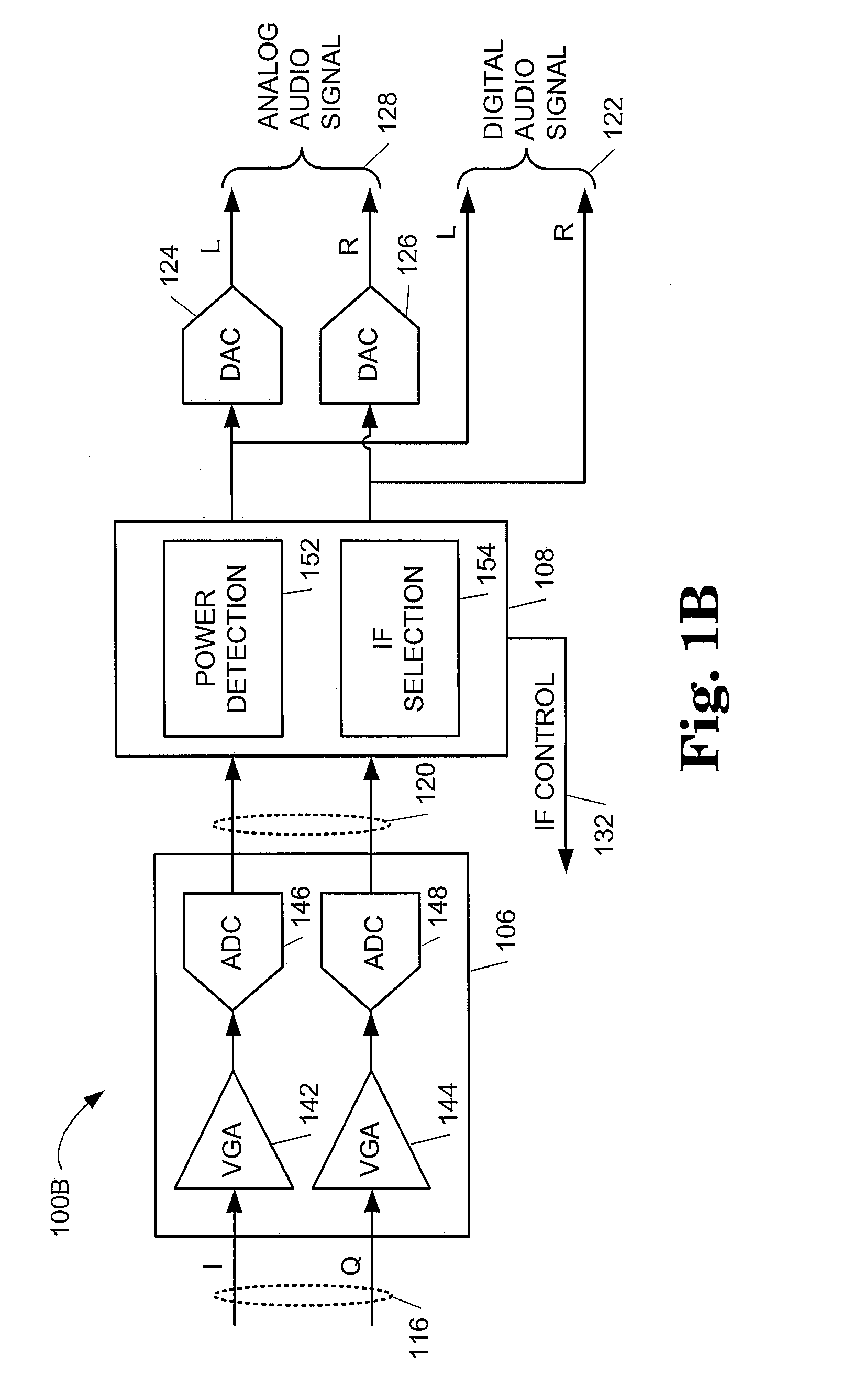
A receiver including a mixer configured to generate a mixed signal at a first intermediate frequency from an input signal and a mixing signal and processing circuitry configured to detect a power level for each of a plurality of possible images in the mixed signal and configured to cause the mixer to generate the mixed signal at a second intermediate frequency that differs from the first intermediate frequency and corresponds to an image frequency of one of the plurality of possible images with a lowest of the power level is provided.

Description

BACKGROUND [0001]Radio frequency (RF) receivers are used in a wide variety of applications such as cellular or mobile telephones, cordless telephones, personal digital assistants (PDAs), computers, radios and other devices that transmit or receive RF signals. As receivers become increasingly integrated and more portable, the efficiency receiving an input signal tends to increase in importance.[0002]Modern receivers often mix a target channel to an intermediate frequency using a mixing signal. As a result of the mixing, an undesired image occurs at an image frequency that can interfere with the target channel. The undesired image can be particularly troublesome where strong spectral content is present at the image frequency. Accordingly, it would be desirable to minimize any interference from a undesired image to maximize the signal selectivity and minimize the signal-to-noise ratio of target channel in a receiver.SUMMARY [0003]According to one exemplary embodiment, a receiver includ...

Claims


Application Information

Patent Timeline
IPC IPC(8): H04B1/16H04B1/18
CPCH03D3/006H04B1/30
Inventor KRONE, ANDREW W.
Owner SILICON LAB INC
Learn More