Radiofrequency ablation device

a radiofrequency ablation and probe technology, applied in the field of radio frequency electrosurgical probes or ablation devices, can solve the problems of reducing the structural integrity of the cannula, cell death and necrosis, and cancerous or malignant tissue necrosis even

Active Publication Date: 2008-10-16
BOSTON SCI SCIMED INC
View PDF12 Cites 29 Cited by
  • Summary
  • Abstract
  • Description
  • Claims
  • Application Information

AI Technical Summary

Problems solved by technology

After deployment, RF energy may be transmitted from the electrode tine array to ablate the target tissue, causing heating and eventual necrosis of cancerous or malignant tissue.
Ionic agitation occurs around an active electrode as a result of frictional heating in the tissue surrounding the electrode tines (e.g., electrodes, RF needle probes, and the like) on an array, leading to cell death and necrosis.
With this last configuration, however, the holes or passageways located within the cannula can reduce the structural integrity of the cannula.

Method used


Image

  • Radiofrequency ablation device
  • Radiofrequency ablation device
  • Radiofrequency ablation device

Examples


Embodiment Construction

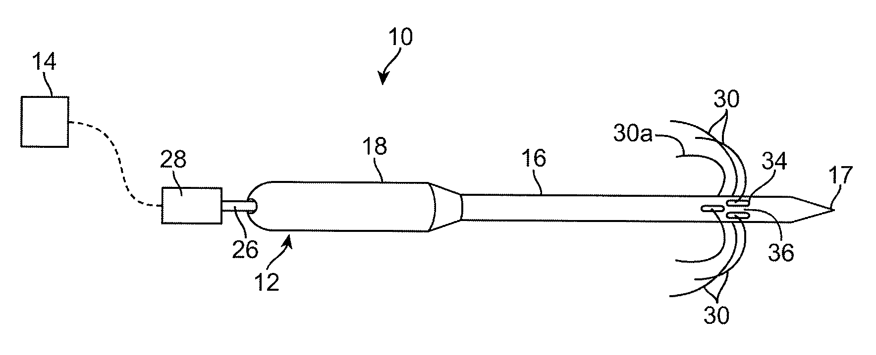
[0020]FIG. 1 illustrates a radiofrequency (RF) ablation device 10 according to one aspect of the invention. As seen in FIG. 1, the RF ablation device 10 includes probe assembly 12 that is configured for introduction into a body of a patient for ablative treatment of target tissue. The target tissue may include, for example, cancerous tissue located within an organ or body tissue. As one illustrative example, the RF ablation device 10 may be used to ablate cancerous tissue located within liver tissue although the invention is not limited to the type of tissue being ablated. The RF ablation device 10 is coupled to a RF generator 14 configured for supplying RF energy to the probe assembly 12 in a controlled manner.

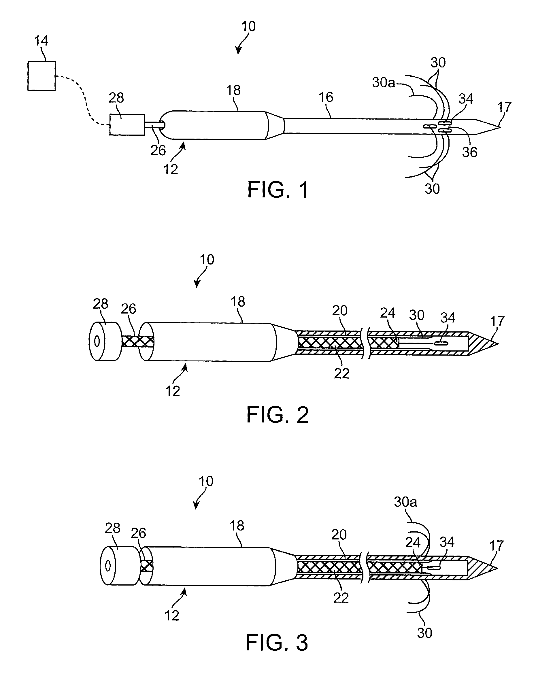
[0021]The probe assembly 12 as seen in FIG. 1, includes an elongate cannula 16 that is coupled to a handle 18 or the like that is used to grip the device 10. The elongate cannula 16 may terminate in a sharpened tip 17 as illustrated in FIGS. 1-3. In still other configurations...


PUM


Abstract

A RF ablation device includes a probe assembly that has an elongate cannula having a lumen disposed interiorly of an external wall of the cannula. The elongate cannula includes a plurality of slots formed within the external wall that provide access to the lumen. The probe assembly includes an electrode member that is slidably disposed within the elongate cannula, the electrode member including a plurality of tines configured for passage through the plurality of slots. The slots are disposed in a staggered arrangement or pattern about the external wall of the cannula. The staggered arrangement of slots may be used in a monopolar or bipolar arrangement of the electrodes on the cannula. A bipolar arrangement of electrodes using the staggered configuration produces larger ablation areas in a shorter period of time as compared to prior designs.

Description

RELATED APPLICATION DATA[0001]The present application claims the benefit under 35 U.S.C. § 119 to U.S. Provisional Patent Application Ser. No. 60 / 911,860, filed Apr. 13, 2007. The foregoing application is incorporated by reference into the present application in its entirety for all purposes.FIELD OF THE INVENTION[0002]The field of the invention generally relates to the structure and use of radio frequency (RF) electrosurgical probes or ablation devices for the treatment of tissue.BACKGROUND OF THE INVENTION[0003]In the field of oncology, cancer treatment is often performed using radio frequency (RF) ablation techniques. Conventional ablation techniques use an array of RF needles or tines (sometimes referred to as a “tine array”), which may be configured to deploy in a pre-determined shape or pattern for transferring RF energy into surrounding tissue. The needles or tines act as electrodes which are electrically connected to a RF generator. The needles or tines thus transmit RF ener...

Claims


Application Information

Patent Timeline
Patent Type & Authority Applications(United States)
IPC IPC(8): A61B18/18
CPCA61B18/1477A61B18/148A61B2018/1465
Inventor YOUNG, KIMBOLTZERFAS, JEFFREY W.PICKETT, STEVEABDULAZIZ, MOHAMED FAZNLHUBBS, GERALD M.
Owner BOSTON SCI SCIMED INC
Why Eureka
Try Eureka