
Display apparatus and method for adjusting brightness thereof

a technology applied in the field of display apparatus and brightness adjustment method, can solve the problems of lcd not being able to display zero-pixel image as a true black image, deterioration of contrast ratio, and difficulty in representing lively images, so as to prevent video signal loss and prevent unnecessary power consumption

Inactive Publication Date: 2008-10-16
SAMSUNG ELECTRONICS CO LTD
View PDF8 Cites 69 Cited by
  • Summary
  • Abstract
  • Description
  • Claims
  • Application Information

AI Technical Summary

Benefits of technology

[0010]The present invention also provides a display apparatus capable of pixel compensation in local areas, to prevent loss of video signal due to a light emitting unit having locally adjusted brightness, and a method for adjusting brightness thereof.
[0011]The present invention also provides a display apparatus capable of adjusting brightness and compensating pixels with respect to an entire screen according to an incoming video signal, and preventing unnecessary power consumption.

Problems solved by technology

Because these types of displays do not generate lights by themselves, they require a separate light source to emit a ray of light.
Images including fireworks or explosions have some parts that need be represented by higher brightness, but due to the absence of counterbalance measures, it is difficult to represent lively images.
Additionally, the light generated at the uniform backlight falls onto the LCD panel, causing interference.
As a result, a LCD is unable to display zero-pixel image as a true black image, and also has degradation of contrast ratio.
Power consumption also increases, because uniform backlight emits the same brightness light even for a dark image which can be represented by a dimmer light.

Method used


Image

  • Display apparatus and method for adjusting brightness thereof
  • Display apparatus and method for adjusting brightness thereof
  • Display apparatus and method for adjusting brightness thereof

Examples


Embodiment Construction

[0046]Certain exemplary embodiments of the present invention will now be described in greater detail with reference to the accompanying drawings.

[0047]In the following description, same drawing reference numerals are used for the same elements even in different drawings. The matters defined in the description, such as the detailed construction and elements, are provided to assist in a comprehensive understanding of the invention. Thus, it is apparent that the present inventive concept can be carried out without those specifically defined matters. Also, well-known functions or constructions are not described in detail since they would obscure the invention with unnecessary detail.

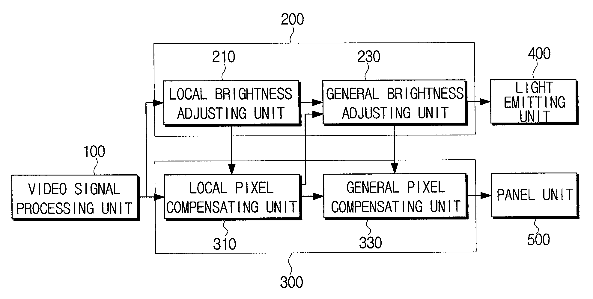
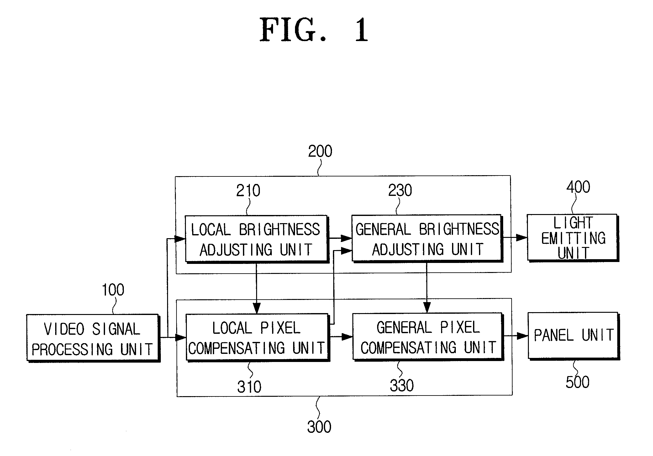
[0048]FIG. 1 is a block diagram of a display apparatus according to an exemplary embodiment of the present invention.

[0049]Referring to FIG. 1, a display apparatus includes a video signal processing unit 100, a light emission control unit 200, a panel control unit 300, a light emitting unit 400, and a panel ...


PUM


Abstract

A display apparatus and a method for adjusting brightness thereof are provided. The display apparatus includes a panel unit which displays a video signal, a light emitting unit which provides the panel unit with a ray of light and causes the video signal to be visualized, a light emission control unit which controls the light emitting unit so that the ray of light is provided to each of local areas of the panel unit, and a panel control unit which compensates pixels of the video signal in each of local areas, to remove an artifact which is generated due to the ray of light provided to local areas of the panel unit. Because brightness of a screen is adjusted in each of local areas, contrast ratio is enhanced, and improved image quality is provided.

Description

CROSS-REFERENCE TO RELATED APPLICATIONS[0001]This application claims priority from Korean Patent Application No. 10-2007-0036065, filed on Apr. 12, 2007, in the Korean Intellectual Property Office, the disclosure of which is incorporated herein by reference in its entirety.BACKGROUND OF THE INVENTION[0002]1. Field of the Invention[0003]Apparatuses and methods consistent with the present invention relate to a display apparatus and a method for adjusting brightness thereof, and, more particularly, to a display apparatus which is capable of adjusting brightness of a screen locally, according to an incoming video signal, and a method for adjusting brightness thereof.[0004]2. Description of the Related Art[0005]Displays such as Liquid Crystal Displays (LCD) in TVs, laptops, or desktops represent images thereon. Because these types of displays do not generate lights by themselves, they require a separate light source to emit a ray of light. An LCD generally has an LCD panel and a light em...

Claims


Application Information

Patent Timeline
IPC IPC(8): G09G5/10G09G3/36G09G3/28G06T5/00G09G3/20G09G3/34H04N1/407H04N1/46H04N1/60
CPCG09G3/2044G09G3/3426G09G2320/0233G09G2320/0238G09G2360/16G09G2320/0261G09G2320/066G09G2320/0673G09G2320/0247G09G3/36G09G3/34G09G3/20G02F1/133
Inventor CHEN, HAN FENGPARK, YUNG-JUNSUNG, JUN-HOCHOI, HOONJUNG, JUN-HO
Owner SAMSUNG ELECTRONICS CO LTD
Learn More