
Piston with pin bore lubrication features

a technology of lubrication features and pin bores, which is applied in the direction of trunk pistons, lubrication elements, and lubricating devices, etc., can solve the problems of reduced bearing area of pin bores, increased load between pin bores and wrist pins, and complicated piston manufacture, etc., to achieve enhanced load capacity of pin bores having lubrication features, maximum load capacity of pin bores, and high performance demands

Active Publication Date: 2008-10-16
FEDERAL MOGUL WORLD WIDE LLC
View PDF15 Cites 13 Cited by
  • Summary
  • Abstract
  • Description
  • Claims
  • Application Information

AI Technical Summary

Benefits of technology

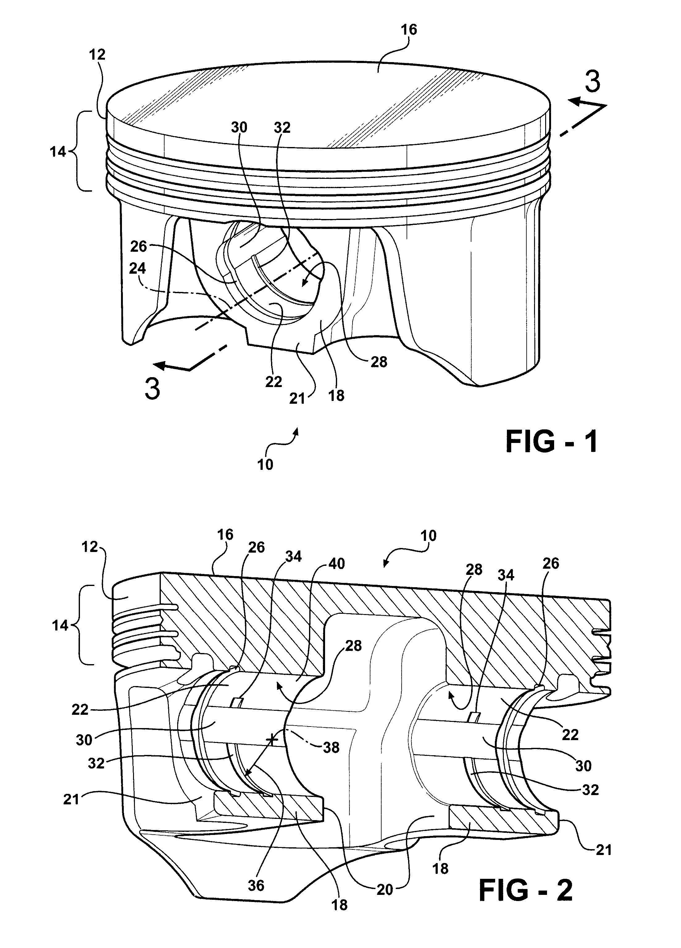
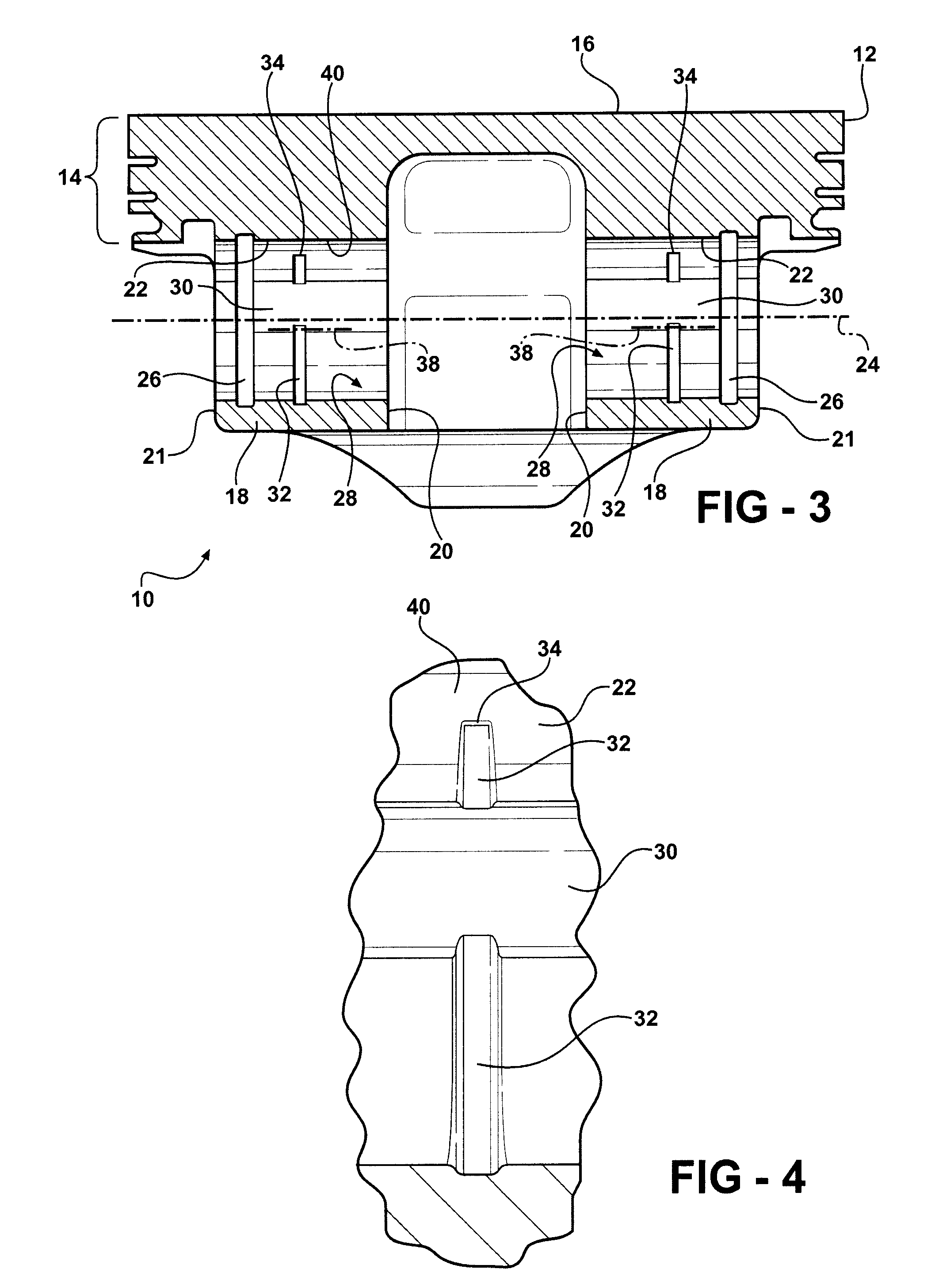
[0007]A piston has a piston body with a crown and a pair of pin bosses having pin bores aligned along a central axis. The pin bores have bearing surfaces with at least one recess extending axially across at least one of said bearing surfaces. A groove extends circumferentially about the bearing surface and is arranged in fluid communication with the recess, wherein the groove terminates at an end within the bearing surface. As such, the bearing surface, while having the recess and groove lubrication features, has an uninterrupted bearing surface portion to maximize the load capacity of the pin bore in the uninterrupted portion.
[0008]Accordingly, the pin bore is able to have a lubrication film layer maintained between its bearing surface and a wrist pin received therein, due to the lubrication features. In addition, the load capacity of the pin bore having the lubrication features is enhance via the uninterrupted bearing surface portion. A piston constructed with the lubrication features is useful in a variety of internal combustion engine applications, including those with high performance demands and space constraints, is economical in manufacture and has an increased useful life.

Problems solved by technology

Although these constructions generally provide suitable lubrication to the pin bores to reduce friction between the pin bores and a wrist pin extending through the pin bores, they reduce the available bearing area of the pin bores, and thus, the loads are increased between the pin bores and the wrist pin.
In addition, the manufacture of the piston is complicated by requiring precise machining to intersect the grooves with the oil ports.

Method used


Image

  • Piston with pin bore lubrication features
  • Piston with pin bore lubrication features
  • Piston with pin bore lubrication features

Examples


Embodiment Construction

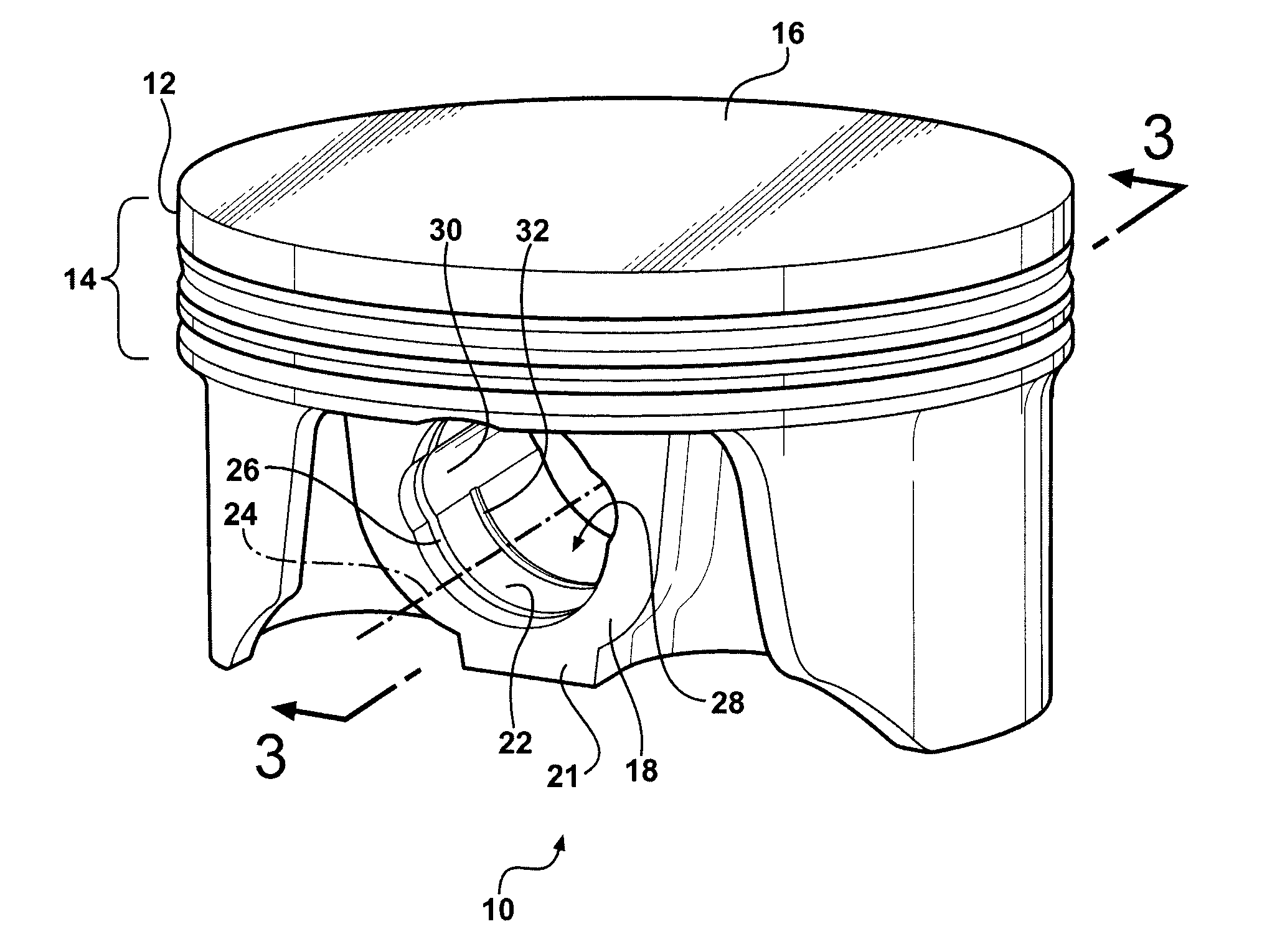
[0018]Referring in more detail to the drawings, FIG. 1 illustrates piston 10 for use in high performance engines, such as those used in racing vehicles and boats, for example. The piston 10 has a crown 12 with an annular outer ring belt 14 extending downwardly from an upper surface 16 and a pair of pin bosses 18 depending from the crown 12. The pin bosses 18 have generally planar inner and outer faces 20, 21, respectively. The inner faces 20 are spaced laterally from one another sufficiently to receive a small end of a connecting rod (not shown) therebetween. The pin bosses 18 have pin bores 22 axially aligned with one another along a central axis 24, wherein the pin bores 22 are sized for receipt of a wrist pin (not shown) to couple the piston 10 to the connecting rod. The pin bores 22 preferably have annular grooves 26 adjacent the outer faces 21 for receipt of snap rings (not shown) to facilitate maintaining the wrist pin in its assembled state. The pin bores 22 have bearing surf...


PUM


Abstract

A piston has a piston body with a pair of pin bosses having pin bores aligned along a central axis. The pin bores have bearing surfaces, wherein at least one recess extends axially across at least one of the bearing surfaces. A groove extends partially about the bearing surface circumference and is arranged in fluid communication with the recess. The recess and groove provide a lubrication feature to the pin bore, while the bearing surface has an uninterrupted portion for enhanced load carrying capacity.

Description

[0001]This application claims priority to U.S. Provisional Application Ser. No. 60 / 910,876, filed Apr. 10, 2007, and is incorporated herein by reference.BACKGROUND OF THE INVENTION[0002]1. Technical Field[0003]This invention relates generally to pistons for internal combustion engines, and more particularly to pistons having lubrication features within a pin bore of the piston.[0004]2. Related Art[0005]It is know to provide a piston for use in an internal combustion engine with lubrication features with axial spaced and aligned pin bores of the piston. Typically, the lubrication features comprise grooves extending about the circumference of the pin bores between opposite sides of the pin bores. Oil ports typically extend from a source of oil supply, such as an oil gallery of the piston, into the associated groove. Although these constructions generally provide suitable lubrication to the pin bores to reduce friction between the pin bores and a wrist pin extending through the pin bor...

Claims


Application Information

Patent Timeline
IPC IPC(8): F01M9/12F02F3/00
CPCF01M11/02F01M2011/025F16J1/08F16J1/16
Inventor HAYES, JAMES RUSSELLDOWDY, GARY D.WILKERSON, JEFFERY D.OVERBEY, JOHN DAVID
Owner FEDERAL MOGUL WORLD WIDE LLC
Learn More